Laminated optical element for touch-sensing systems

a technology of touch sensor and optical element, applied in the field of touch sensor, can solve the problems of affecting the user experience, difficult and/or costly to achieve, and the change of light received by one or more detectors, and achieve the effect of convenient user interfa

Inactive Publication Date: 2015-11-19
FLATFROG LAB
View PDF18 Cites 49 Cited by
  • Summary
  • Abstract
  • Description
  • Claims
  • Application Information

AI Technical Summary

Benefits of technology

[0010]More specifically, one objective is to provide an optical element for an FTIR-based touch-sensitive apparatus, which is robust and compact, while providing a convenient user interface.

Problems solved by technology

An object that touches one of the boundary surfaces (“the touch surface”) will attenuate (“frustrate”) the light on one or more propagation paths and cause a change in the light received by one or more of the detectors.
This may be difficult and / or costly to achieve, especially if the panel is thin and / or manufactured from a comparatively brittle material such as glass.
In-coupling via the edge surface may also add to the footprint of the touch system.
Furthermore, it may be difficult to optically access the edge surface if the panel is attached to a mounting structure, such as a frame or bracket, and it is also likely that the mounting structure causes strain in the edge surface.
However, the prisms or wedges may add significant thickness and weight to the system.
The present applicant has found that the difference in thermal expansion between the plastic material and the glass may cause a bulky wedge to come loose from the panel as a result of temperature variations during operation of the touch system.
Even a small or local detachment of the wedge may cause a significant decrease in the performance of the system.

Method used


Image

  • Laminated optical element for touch-sensing systems
  • Laminated optical element for touch-sensing systems
  • Laminated optical element for touch-sensing systems

Examples


Embodiment Construction

[0043]In the following, embodiments of the present invention will be presented for an example of a laminated optical element, as well as a touch-sensitive apparatus incorporating such a laminated optical element. Throughout the description, the same reference numerals are used to identify corresponding elements.

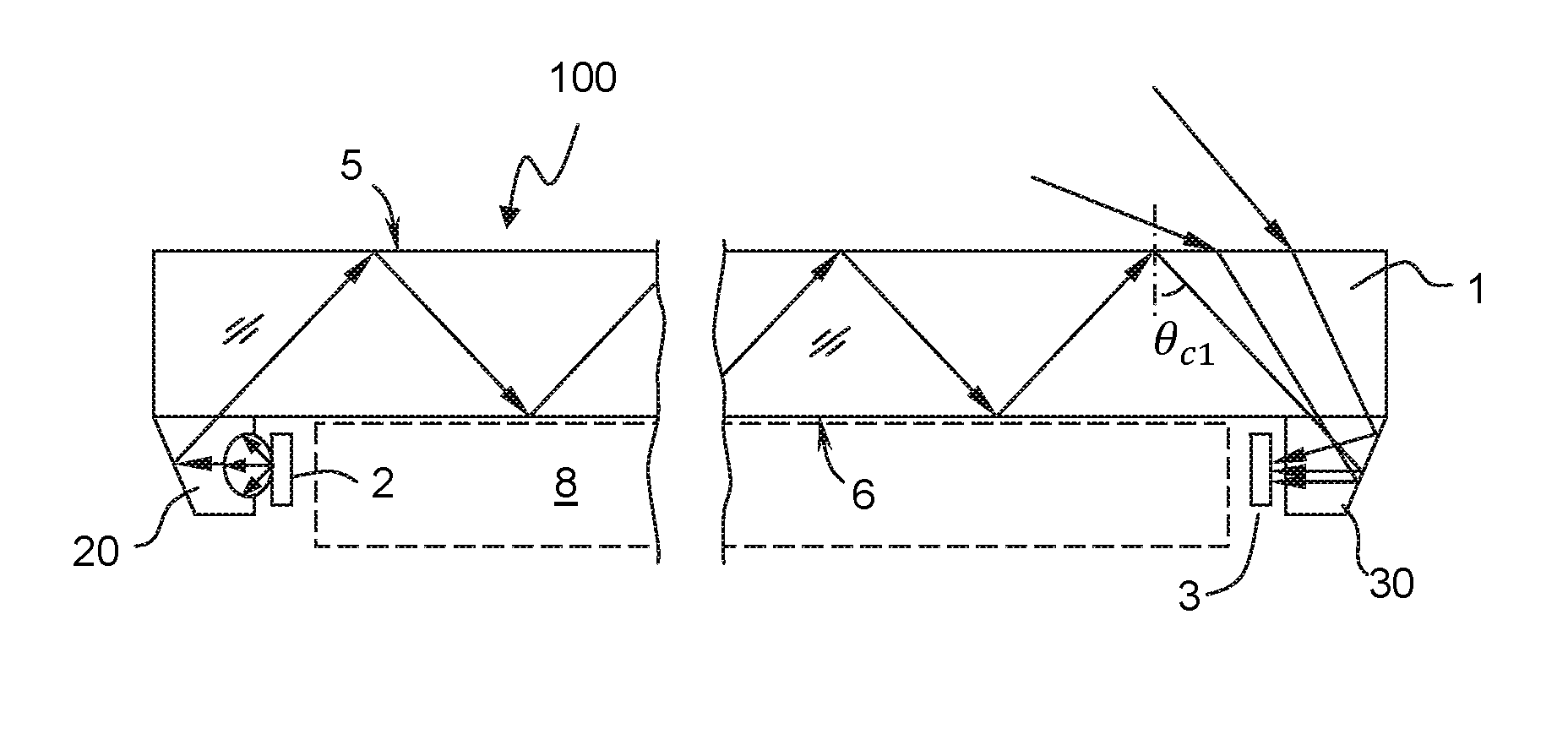
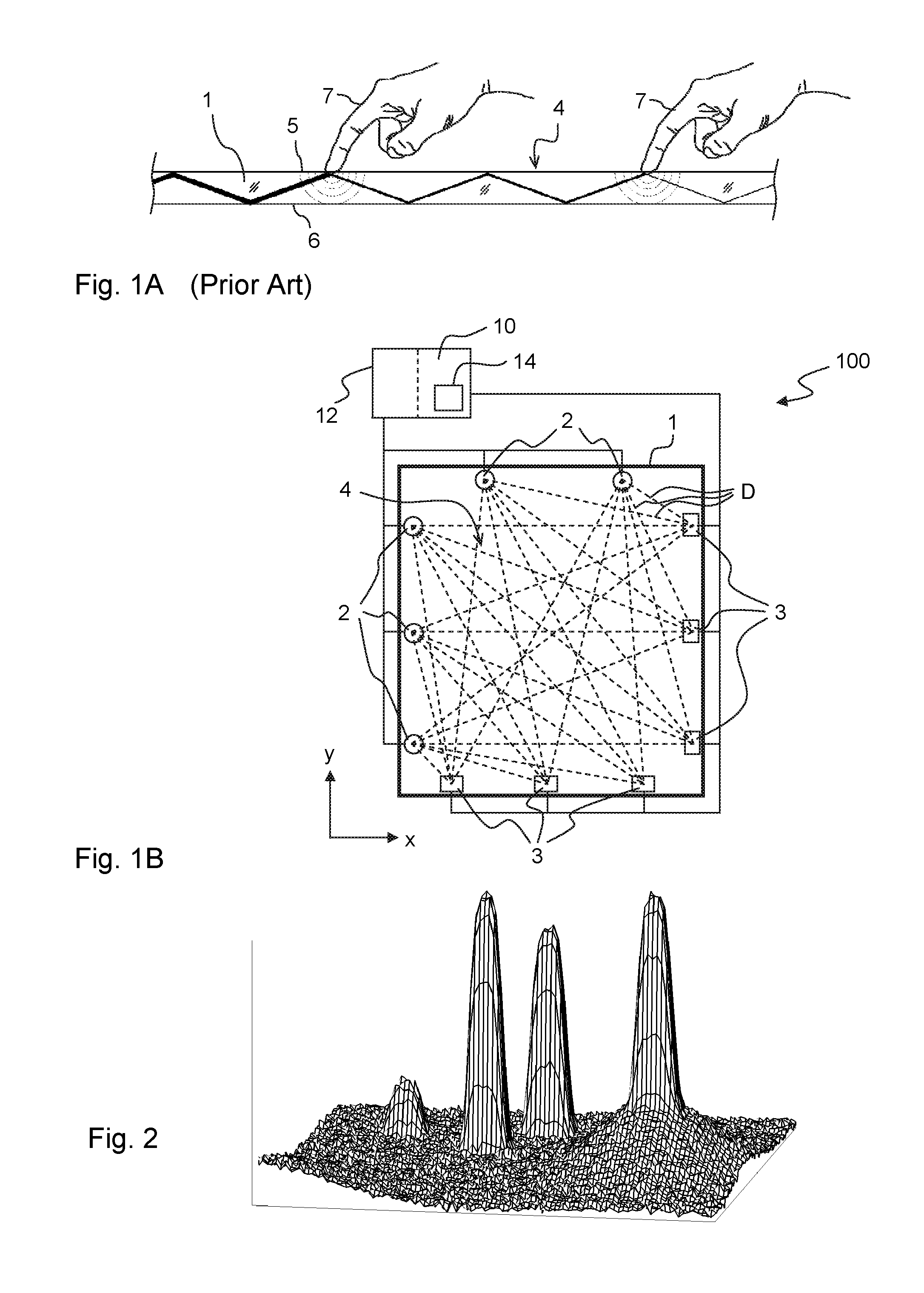
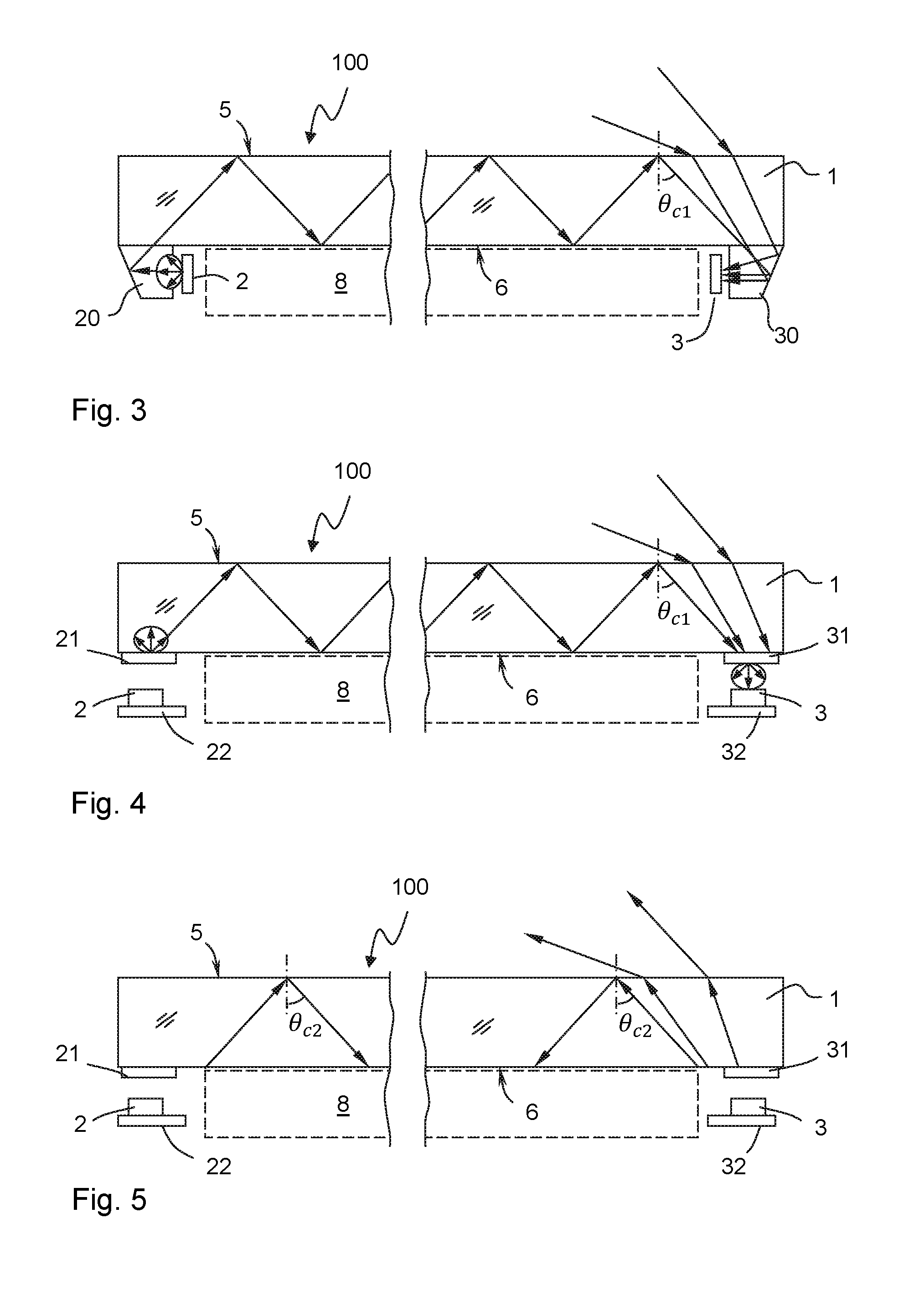
[0044]FIG. 1A illustrates the concept of touch detection based on attenuation by FTIR (Frustrated Total Internal Reflection) of propagating light. According to this concept, light is transmitted inside a panel 1 along a plurality of well-defined propagation paths. The panel 1 is made of a solid material in one or more layers and may have any shape. The panel 1 defines an internal radiation propagation channel, in which light propagates by internal reflections. In the example of FIG. 1A, the propagation channel is defined between the boundary surfaces 5, 6 of the panel 1, and the front (top) surface 5 allows the propagating light to interact with touching objects 7 and thereby...


PUM


Abstract

A laminated optical element is provided for a touch-sensitive apparatus which operates by light frustration (FTIR), and comprises: a light-transmissive panel (1) that defines a front surface (5) and an opposite, rear surface (6); a light-coupling mechanism for light input to and output from the panel, arranged along a perimeter of a touch-sensitive region (4) of the optical element; a shielding element (70) applied at the front surface (5) over the light-coupling mechanism; and a light-transmissive sheet (60) disposed overlapping the shielding element and covering the front surface of the panel within the shielding element, wherein a lower surface of the light-transmissive sheet is in optical contact with the front surface of the panel, so as to allow light within a predetermined wavelength range to propagate between at least first and second positions of the light-coupling mechanism by total internal reflection in an upper surface of the light-transmissive sheet.

Description

CROSS-REFERENCE TO RELATED APPLICATIONS[0001]The present application claims the benefit of Swedish patent application No. 1251439-4, filed 17 Dec. 2012, and U.S. provisional application No. 61 / 738,035, filed 17 Dec. 2012, both of which are incorporated herein by reference.TECHNICAL FIELD[0002]The present invention relates to the field of touch-sensing systems that operate by propagating light by internal reflections along well-defined light paths inside a thin light-transmissive panel, and in particular to solutions for providing a robust and user friendly optical element for such a touch-sensing system.BACKGROUND ART[0003]This type of touch-sensing system is known as an FTIR-based system (FTIR, Frustrated Total Internal Reflection). It may be implemented to operate by transmitting light inside a solid light-transmissive panel, which defines two parallel boundary surfaces connected by a peripheral edge surface. Light generated by a plurality of emitters is coupled into the panel so ...

Claims


Application Information

Patent Timeline
Patent Type & Authority Applications(United States)
IPC IPC(8): G06F3/042G02B6/42
CPCG06F3/0421G02B6/4214G06F2203/04103G06F2203/04109G06F2203/04104G06F3/042
Inventor WASSVIK, OLABERGSTROM, HAKANCRAVEN-BARTLE, THOMASF HRAEUS, CHRISTER
Owner FLATFROG LAB
Why Eureka
Try Eureka