Method for Controlling Acoustic Echo Cancellation and Audio Processing Apparatus
- Summary
- Abstract
- Description
- Claims
- Application Information
AI Technical Summary
Benefits of technology
Problems solved by technology
Method used
Image
Examples
first embodiment
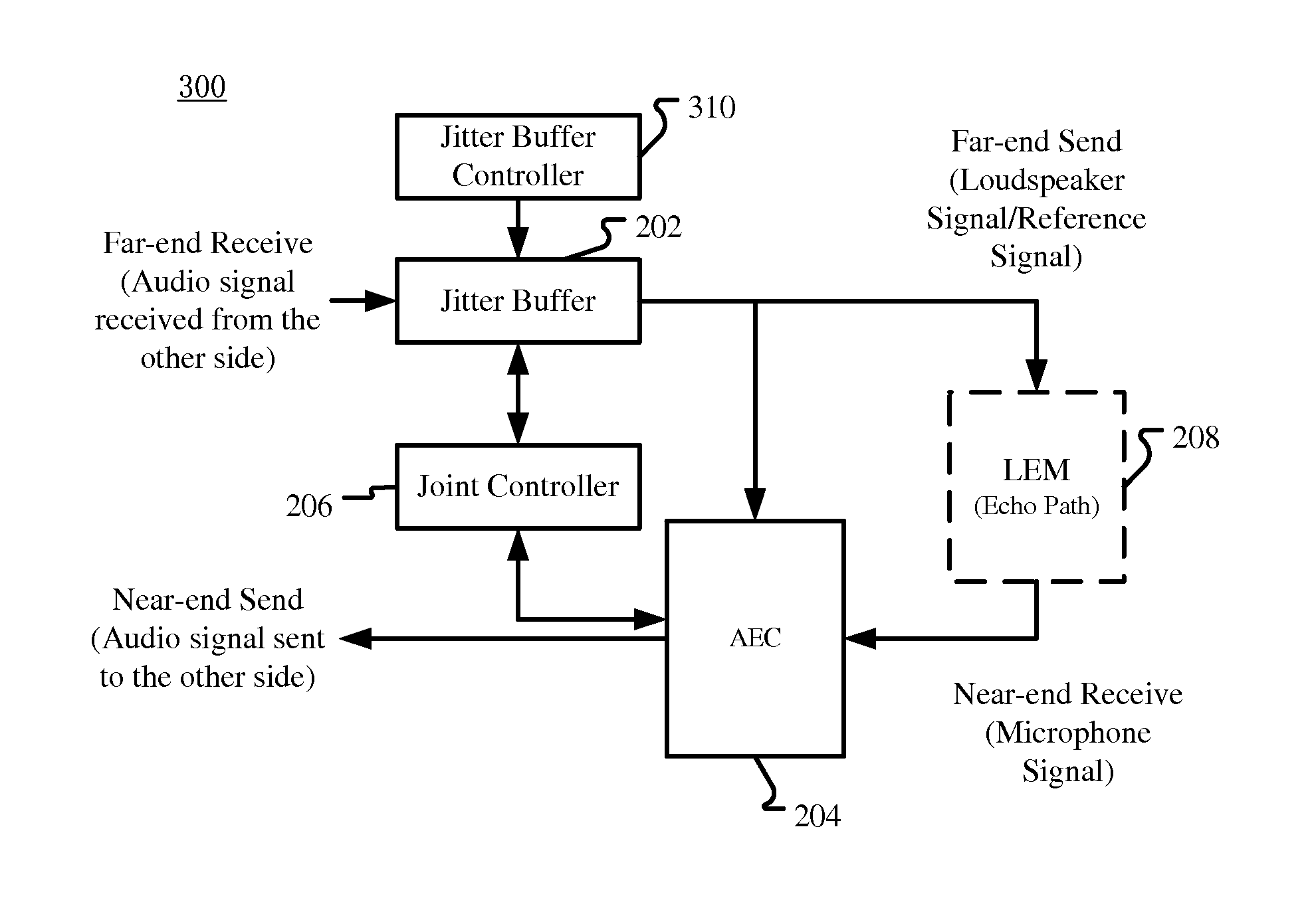
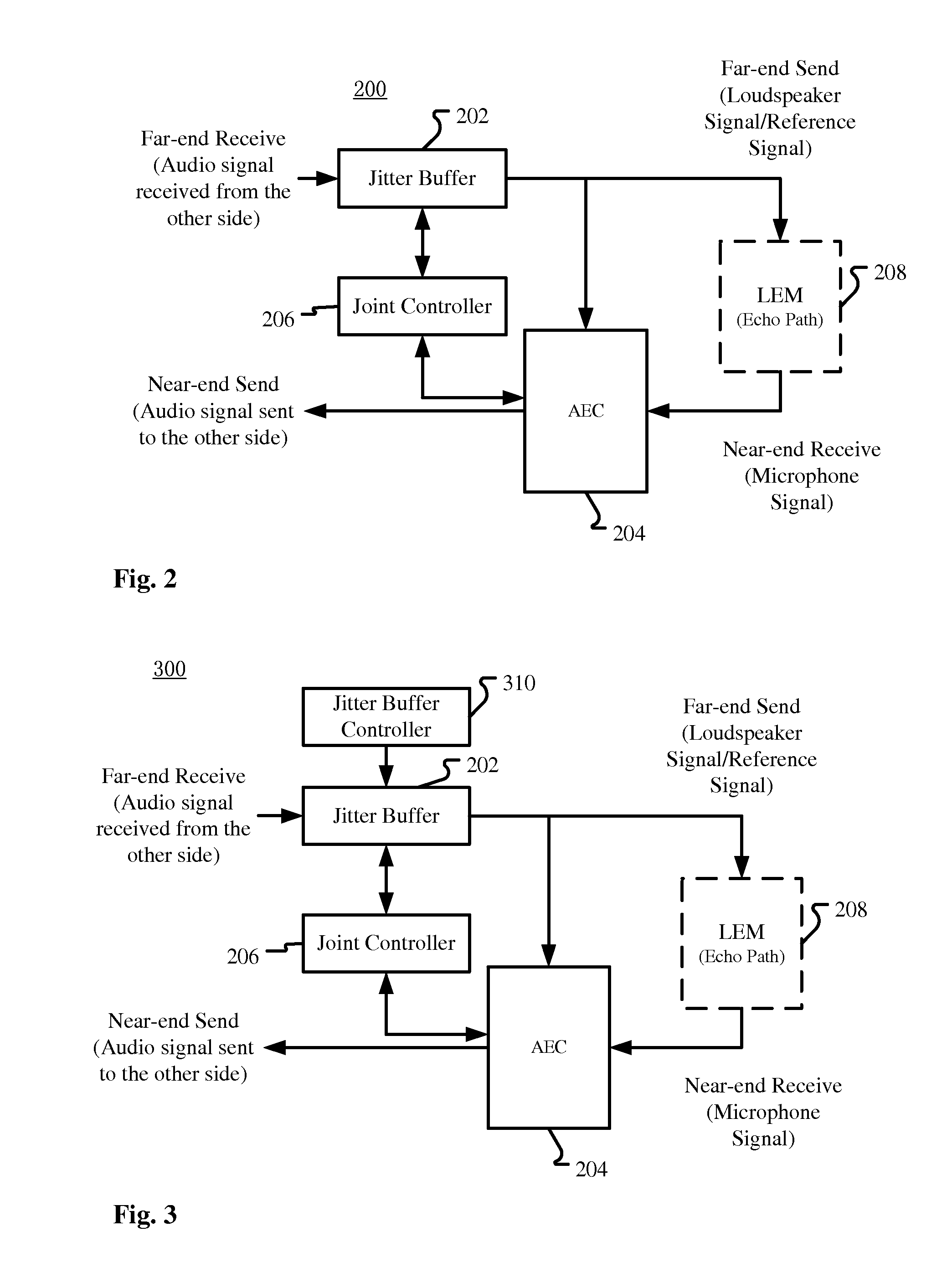
[0033]As shown in FIG. 2, an audio processing apparatus 200 comprises an acoustic echo canceller (AEC) 204 for suppressing acoustic echo in a microphone signal; a jitter buffer (JB) 202 for reducing delay jitter of a received signal; and a joint controller 206 for controlling the acoustic echo canceller by referring to at least one future frame in the jitter buffer.
[0034]In this embodiment, as in conventional solutions, AEC separates and filters out from the microphone signal the loudspeaker signal transmitted by LEM (Loudspeaker-Enclosure-Microphone, that is, the echo path) 208 and distorted by a transfer function of the LEM 208. However, according to the embodiment of the present application, a joint controller 206 is provided for controlling the AEC based on at least one future frame already received in the JB 202. Such control may include adjusting convergence rate and / or step size of the adaptive filter in the AEC, adjusting the threshold in a center clipper in the AEC, and / or...
second embodiment
[0043] the acoustic echo canceller 204 comprises an adaptive filter 2042, and the joint controller 206 is configured to increase or decrease a convergence rate of the adaptive filter in response to increasing or decreasing of the signal intensity of the at least one future frame, respectively.
[0044]For example, if the next one or several frames have very low energy, we could decrease the convergence rate in anticipating weak echo in the microphone signal to slow down the adaptation. When the echo is weak, the microphone signal is likely to be dominated by ambient noise or near end speech. Thus slowing down adaptation in this case would avoid filter divergence. Similarly, when the next one or several frames have high energy speech signals, the convergence rate would be increased in anticipating strong echo in the microphone signal.
[0045]Most of the acoustic echo cancellers are based on NLMS (Normalized Least Mean Squares)-based adaptive filtering algorithms. Let X(ω,t), D(ω,t), ω and...
third embodiment
[0060] the acoustic echo canceller 204 comprises a center clipper 2044 for suppressing residual echo; and the joint controller 206 is configured to increase or decrease a threshold of the center clipper 2044 in response to increasing or decreasing of the signal intensity of the at least one future frame, respectively.
[0061]In real world applications, nonlinearities commonly exist in the echo path, which are often due to overdriven loudspeaker signals. Non-linear processing such as center clipping is often used. In such methods, a predefined threshold is used where samples amplitude below this threshold are set to zero. This threshold is often tunable and adaptive. When future frames available, better adaptation of this threshold can be achieved. If the future frames are of high energy, this threshold can be set higher accordingly in anticipating future processed microphone signal will contain more residual echo.
[0062]In one conventional embodiment, when no future frames are availabl...
PUM
 Abstract
Description
Claims
Application Information
 - R&D
- Intellectual Property
- Life Sciences
- Materials
- Tech Scout
- Unparalleled Data Quality
- Higher Quality Content
- 60% Fewer Hallucinations
Browse by: Latest US Patents, China's latest patents, Technical Efficacy Thesaurus, Application Domain, Technology Topic, Popular Technical Reports.
© 2025 PatSnap. All rights reserved.Legal|Privacy policy|Modern Slavery Act Transparency Statement|Sitemap|About US| Contact US: help@patsnap.com


