Power Strut

a technology of power struts and struts, which is applied in the direction of door/window fittings, electrical equipment, dynamo-electric machines, etc., can solve the problems of limit the output power of motors, and achieve the effects of simplifying the structure, reducing fabrication costs, and eliminating the outer housing of magnetically conductive materials

Inactive Publication Date: 2015-11-19
JOHNSON ELECTRIC SA
View PDF16 Cites 7 Cited by
  • Summary
  • Abstract
  • Description
  • Claims
  • Application Information

AI Technical Summary

Benefits of technology

[0008]Preferably, a recessed mounting portion is formed in an outer periphery of the magnet mounting bracket and the end cover, and the driver sleeve forms a mounting portion interference-fitting with the recessed mounting portion to prevent relative movement between the magnet mounting bracket and the driver sleeve.
[0019]In view of the foregoing, the permanent magnets of the motor assembly fit against the inner surface of the driver sleeve, and the permanent magnets and the sleeve cooperatively form the closed magnetic loop. This eliminates the magnetically conductive outer housing of the motor, thus simplifying the structure and reducing the fabrication cost. In addition, because of the elimination of the motor housing, the radial space available in the driver sleeve is increased, which enables a greater outer diameter of the motor rotor and hence increases the power of the motor.

Problems solved by technology

This places a limitation on the output power of the motor.

Method used


Image

  • Power Strut
  • Power Strut
  • Power Strut

Examples


Embodiment Construction

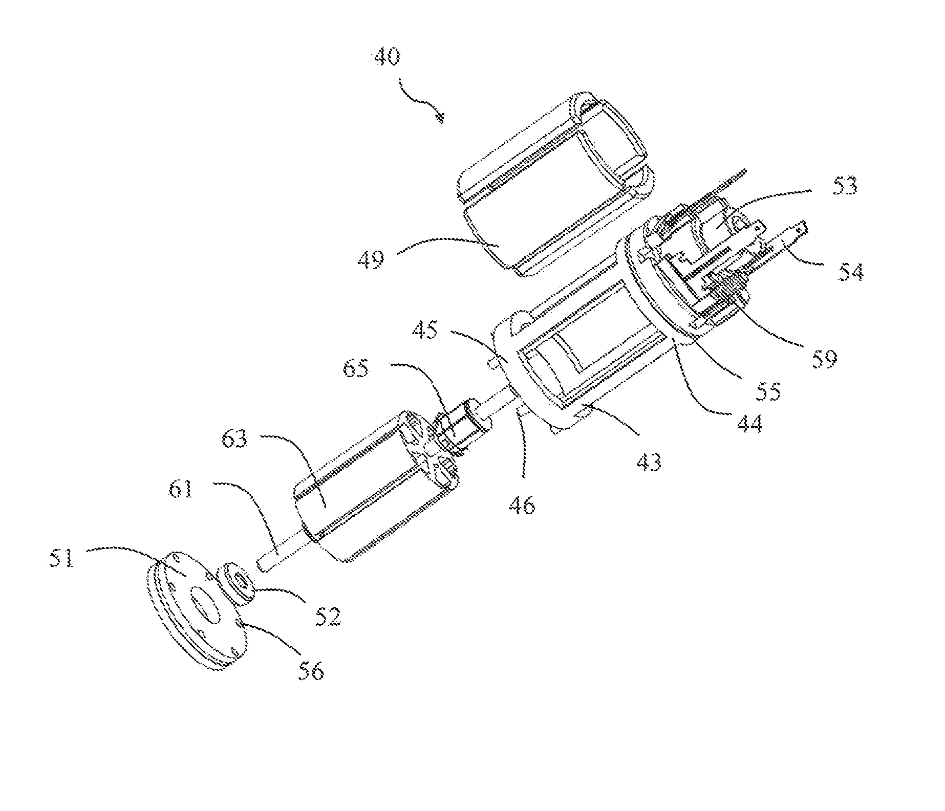
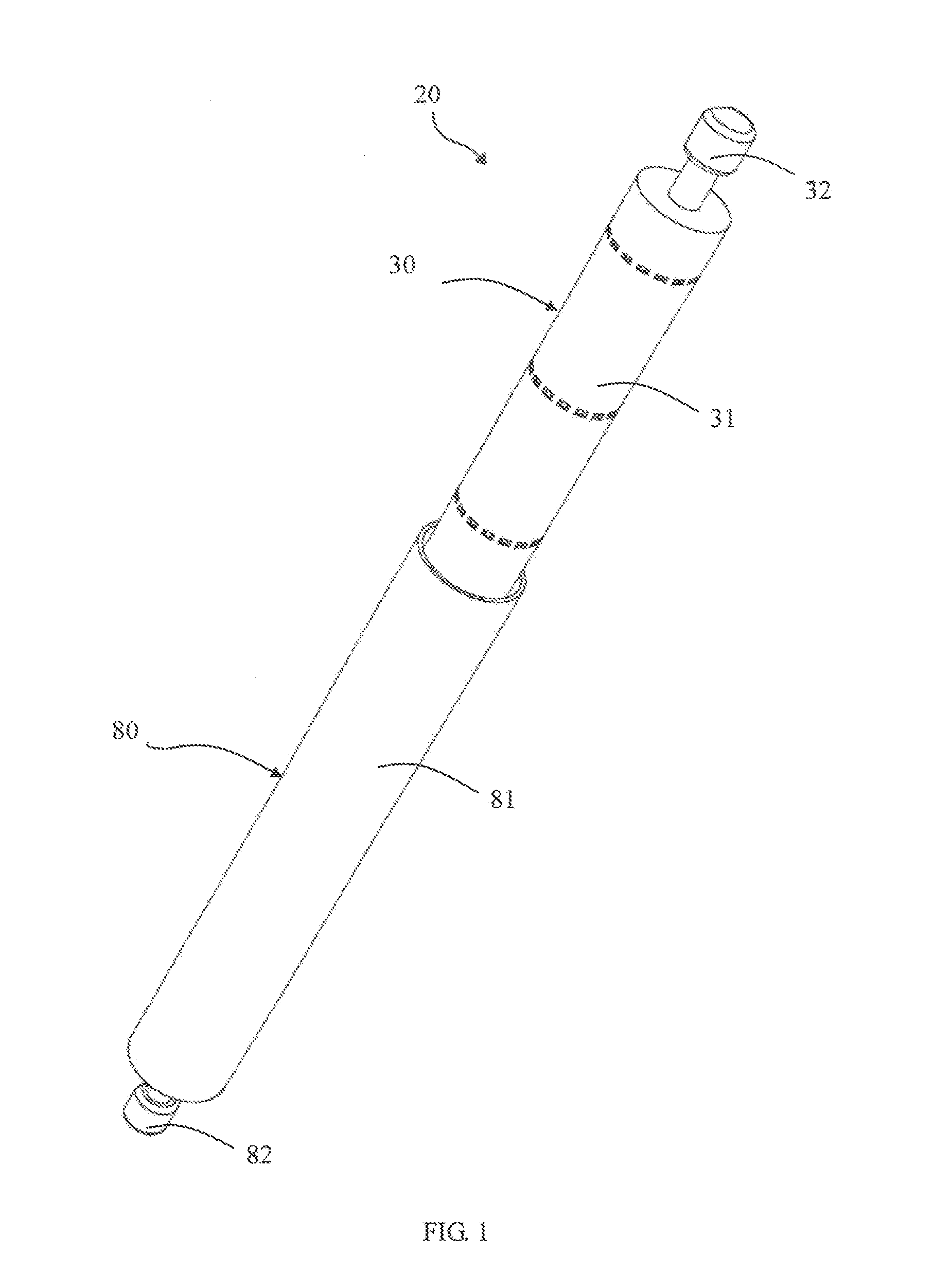
[0028]Referring to FIG. 1 through FIG. 3, a power strut 20 for a lift gate of a vehicle in accordance with the preferred embodiment of the present invention includes a driver 30 and a lead screw device 80 connected to the driver 30. The driver 30 includes a driver sleeve 31, a first connecting head 32 at one end of the driver sleeve 31, and a motor assembly 40 and a gear train or gear reduction mechanism 70 received in the driver sleeve 31. The gear reduction mechanism 70 is connected to the motor assembly 40 to reduce the speed of the motor output while increasing the output torque. The lead screw device 80 includes a lead screw sleeve 81, a second connecting head at one end of the lead screw sleeve 81, a lead screw 84 mounted in the lead screw sleeve 81, and a spring 86. The lead screw 84 is driven by the gear reduction mechanism 70. The lead screw 84 engages with a nut 83 for converting rotation of the lead screw 84 into linear movement of the nut 83. The nut 83 is fixed relative...


PUM


Abstract

A power strut for a vehicle lift gate, has a driver sleeve, a lead screw sleeve, a lead screw and a spring mounted in the lead screw sleeve. A gear reduction mechanism and a motor assembly are mounted in the driver sleeve for driving the lead screw. The motor assembly has a magnet mounting bracket fixed to the driver sleeve and a rotor disposed in the magnet mounting bracket. An end cover and multiple permanent magnets are fixed to the magnet mounting bracket. Each of the magnets is positioned between a corresponding pair of adjacent connecting portions and contacts an inner surface of the driver sleeve, thereby the driver sleeve provides a magnetic path between the magnets.

Description

CROSS REFERENCE TO RELATED APPLICATIONS[0001]This non-provisional patent application claims priority under 35 U.S.C. §119(a) from Patent Application No. 201410206864.9 filed in The People's Republic of China on May 15, 2014, the entire contents of which are hereby incorporated by reference.FIELD OF THE INVENTION[0002]This invention relates to an electric actuator and in particular, to a power strut as used for raising and lowering a hatch door of a vehicle.BACKGROUND OF THE INVENTION[0003]Some vehicles have a hatch door for access to the rear of the vehicle. This is a door which is raised and lowered by swinging or pivoting in the vertical direction and is also known as a lift gate as it is commonly used in vans and light goods vehicles to provide access to the cargo area of the vehicle. Manually operated lift gates have one or two struts with provide a spring force to assist opening. Power struts have an electric motor used to extend and retract the strut to open and close the lift...

Claims


Application Information

Patent Timeline
Patent Type & Authority Applications(United States)
IPC IPC(8): H02K5/16H02K1/22H02K1/17H02K5/22H02K13/10H02K7/08H02K7/116H02K7/14H02K13/00E05F15/622H02K7/06
CPCH02K5/163E05F15/622H02K1/22H02K1/17H02K5/22E05Y2900/546H02K7/083H02K7/116H02K7/14H02K13/006H02K13/10H02K7/06
Inventor CHEONG, MAN IAOGOROSIN, DENNIS FRANCISLI, XUE SONGGAN, XIAO FUXIONG, HUI MIN
Owner JOHNSON ELECTRIC SA
Why Eureka
Try Eureka