Processing apparatus, processing system, and processing method

Inactive Publication Date: 2015-11-19
RICOH KK
View PDF5 Cites 117 Cited by
  • Summary
  • Abstract
  • Description
  • Claims
  • Application Information

AI Technical Summary

Benefits of technology

[0011]It is an object of the present invention to at least

Problems solved by technology

Examples of the dangerous situation include sudden braking of the vehicle traveling ahead, another car coming in between the user's vehicle and the vehicle traveling ahead, and a pedestrian running into the road.
However,

Method used


Image

  • Processing apparatus, processing system, and processing method
  • Processing apparatus, processing system, and processing method
  • Processing apparatus, processing system, and processing method

Examples


first embodiment

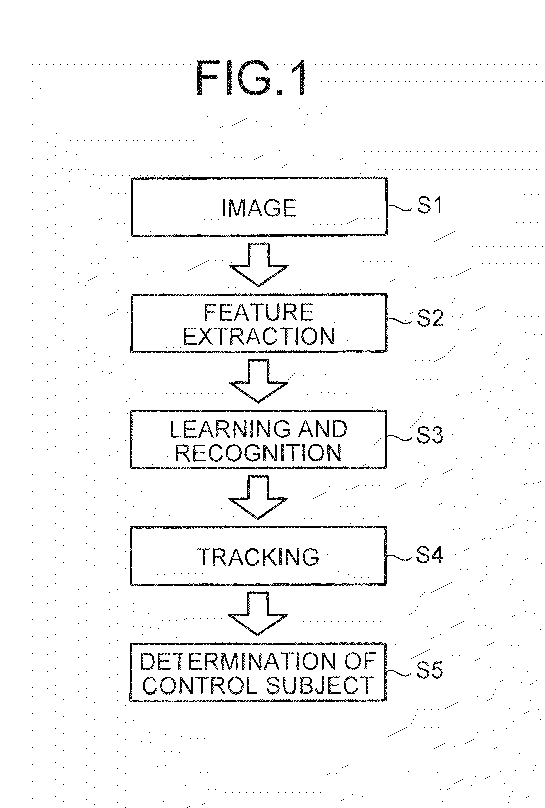
[0046]Illustrated first in FIG. 1 is a procedure of a general case of a three-dimensional object recognition processing. As illustrated in FIG. 1, the general case of three-dimensional object recognition processing includes acquiring images captured by, for example, a camera apparatus at step S1, and extracting feature points from the acquired images at step S2. The processing further includes recognizing objects from the feature points at step S3, and tracking each of the objects while checking the correspondence of the centroids of the recognition-target objects with the recognition history of the centroids of the thus far recognition-target objects at step S4. For example, when a control subject to be controlled with the recognition result is an automatic braking system, the processing further includes performing control, such as automatic braking, depending on the recognition results for the respective objects, at step S5.

[0047]When such three-dimensional object recognition proc...

second embodiment

[0112]The following describes another three-dimensional object recognition apparatus as a second embodiment. In the first place, the three-dimensional object recognition apparatus of the second embodiment uses a “background model (background information (stationary object) model) in which stationary objects in the background of moving objects are modeled”, a “road (traveled surface) model” and “recognition histories of the respective moving objects” to grasp information such as what scene situation each object set as a control subject is currently under, whether there is any object previously detected, and what state each previously-detected object is under the current scene situation. Then, the three-dimensional object recognition apparatus detects moving objects (recognition targets) while changing detection methods in accordance with the grasped circumstances.

[0113]More specifically, the three-dimensional object recognition apparatus of the second embodiment uses a modeled enviro...

third embodiment

[0132]The following describes another three-dimensional object recognition apparatus as a third embodiment. The three-dimensional object recognition apparatus of the third embodiment determines a danger level based on the current situation of the user's vehicle, and performs control, such as speed control or steering wheel control, on the user's vehicle in accordance with the determination result. FIG. 17 illustrates a functional block diagram of functions that are implemented when the CPU 15 in the three-dimensional object recognition apparatus of the third embodiment operates in accordance with the three-dimensional object recognition program. As illustrated in FIG. 17, the three-dimensional object recognition apparatus of the third embodiment includes a three-dimensional information generator 86, a three-dimensional structure recognizer 87, an image recognizer 88, a scene recognizer 89, a situation predictor 90, a situation recognizer 91, a new-object detector 92, and a danger-le...


PUM


Abstract

A processing apparatus includes a distance image acquirer, a moving-object detector, and a danger-level determining unit. The distance image acquirer acquires a distance image containing distance information of each pixel. The moving-object detector detects a moving object from the distance image. The danger-level determining unit determines a danger level of the moving object by use of the distance image, and outputs the danger level to a controller that controls a controlled unit in accordance with the danger level.

Description

CROSS-REFERENCE TO RELATED APPLICATIONS[0001]The present application claims priority to and incorporates by reference the entire contents of Japanese Patent Application No. 2014-103838 filed in Japan on May 19, 2014, Japanese Patent Application No. 2014-103836 filed in Japan on May 19, 2014 and Japanese Patent Application No. 2015-81177 filed in Japan on Apr. 10, 2015.BACKGROUND OF THE INVENTION[0002]1. Field of the Invention[0003]The present invention relates to a processing apparatus, a processing system, and a processing method.[0004]2. Description of the Related Art[0005]In recent years, moving-object recognition apparatuses have been developed, which recognize a speed and a change in movement of a moving object such as a vehicle traveling ahead of a user's vehicle or a pedestrian, detect a dangerous situation in its early stage, and notify a driver thereof so as to avoid the danger. Examples of the dangerous situation include sudden braking of the vehicle traveling ahead, anoth...

Claims


Application Information

Patent Timeline
IPC IPC(8): H04N5/14G06T7/20B60W30/08H04N5/232
CPCH04N5/145H04N5/147H04N5/23254H04N5/23264G06T7/2006B60W2550/10G06T2207/10016G06T2207/30236G06T2207/30241B60W2420/42B60W30/08H04N5/14G06T2207/10021G06T2207/10028G06T2207/30261G06T7/251G06T7/277B60W2050/143B60K2370/21B60K2370/52B60K2370/77B60K2370/334B60W50/14B60W2554/00G06V20/58G06V20/56H04N23/60B60W2554/80B60W2754/10G06V40/20H04N23/682H04N23/6811B60W2554/4026B60W2554/20B60W2554/4029B60R1/00B60R2300/105B60R2300/107B60R2300/205B60R2300/301B60R2300/302B60R2300/303B60W30/09B60W30/143B60W2050/146B60W2510/18B60W2510/20B60W2520/105B60W2520/14B60W2710/18B60W2710/20B60W2720/106B60W2720/14G06T11/60G08G1/166
Inventor YOKOTA, SOICHIROISHIGAKI, TOMOKOSEKIGUCHI, HIROYOSHISAISHO, KENICHIROH
Owner RICOH KK
Why Eureka
Try Eureka