

Flipper
- Summary
- Abstract
- Description
- Claims
- Application Information
AI Technical Summary
Benefits of technology
Problems solved by technology
Method used
Image

Examples
first embodiment
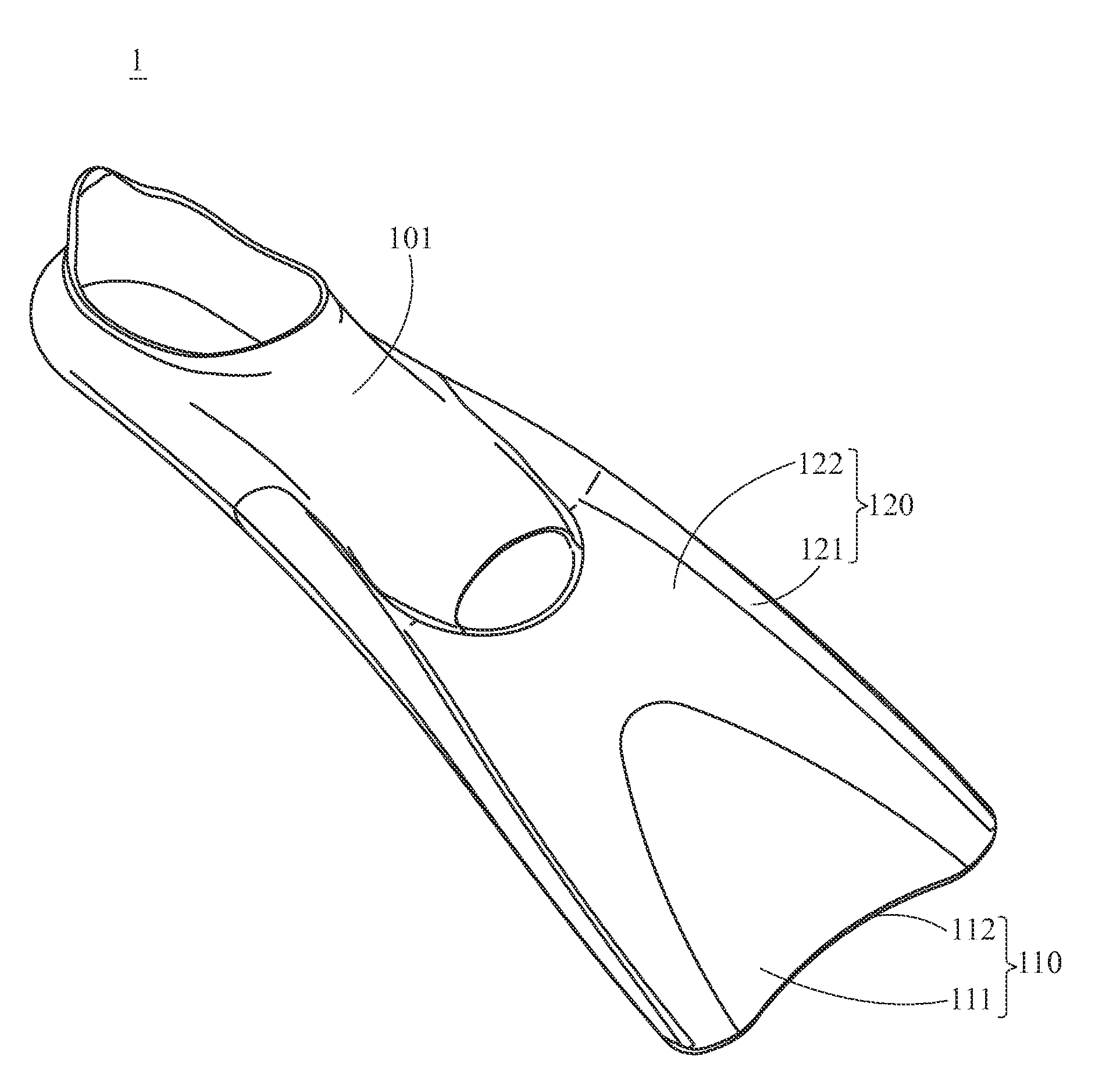
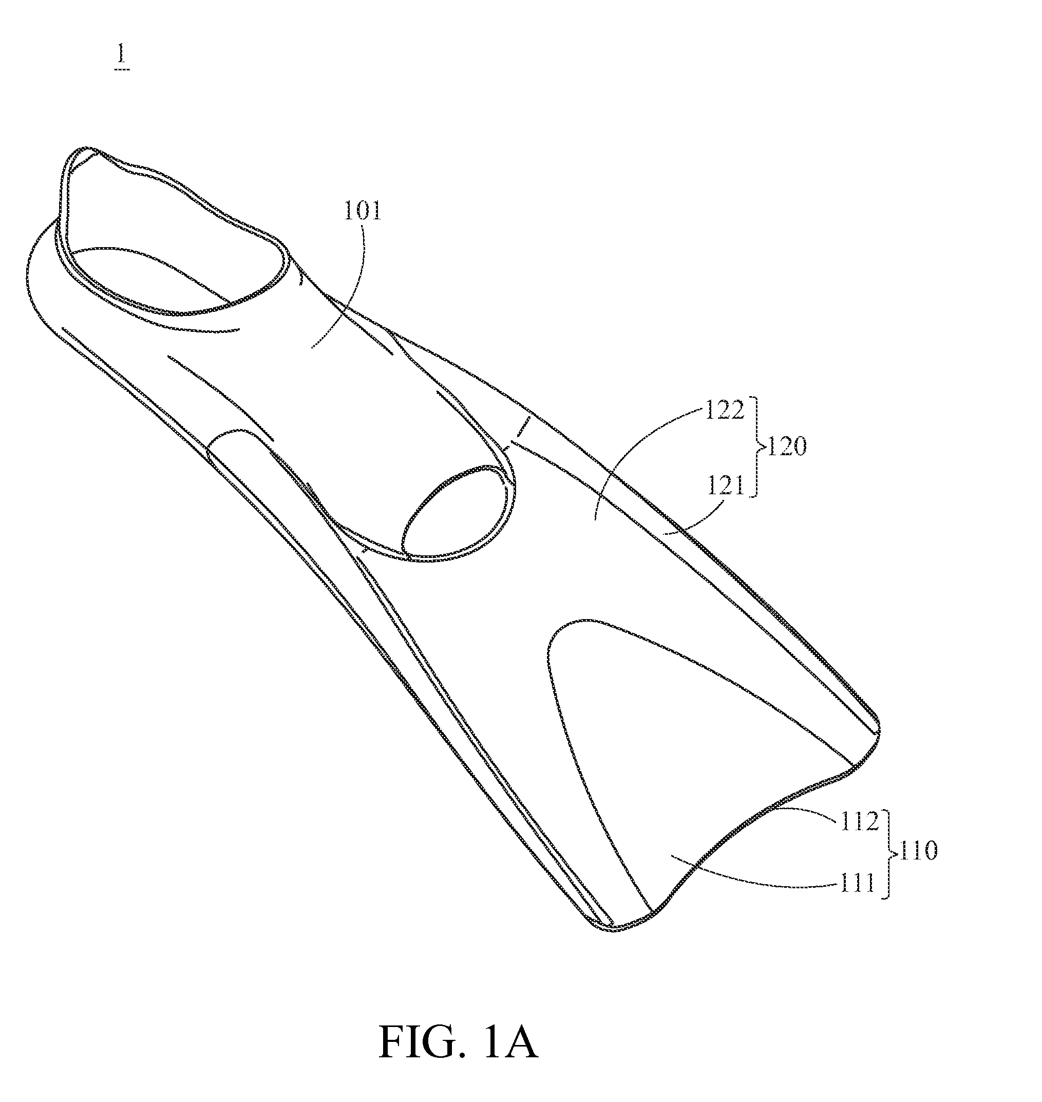
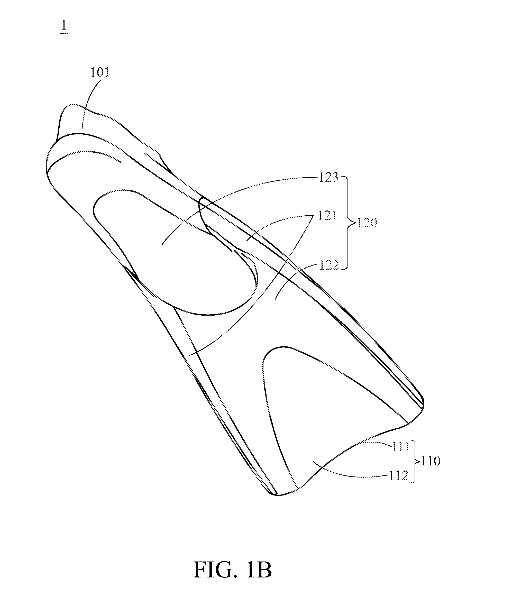
[0029]FIGS. 1A and 1B show a schematic front view and a schematic back view of a flipper according to the present invention respectively. The present invention provides a flipper 1, which comprises a pocket 101, a blade 110 and a strengthening structure 120. The pocket 101 is adapted to accommodate the foot of the user just like a shoe or a sock, and selectively accommodates the ankle of the user. The blade 110 is roughly fan-shaped or tabular structure and extends forwards from the pocket 101.
[0030]The strengthening structure 120 is detachably disposed at the blade 110 and extends to reach the front edge of the blade 110. The strengthening structure 120 may extend beyond or somewhat behind the front edge of the blade 110. In this embodiment, the strengthening structure 120 extends just to reach the front edge of the blade 110. The strengthening structure 120 may be disposed on the top surface 111 or bottom surface 112 of the blade 110, or alternatively, there may be two strengtheni...
fourth embodiment
[0050]FIG. 4C shows a schematic view of the swing-constraining structure of the flipper according to the present invention. In this embodiment, the swing-constraining structure 430 may be disposed on the pocket 401 pivotally, but will not swing with respect to the strengthening structure 420.
[0051]The pocket 401 has two pivots 401a that are disposed on the two sides of the pocket 401 respectively. The swing-constraining structures 430 are affixed on the pocket 401 via the respective pivots 401a and are pivotable around the respective pivots 401a with respect to the pocket 401. Each of the pivots 401a further has a protrusion 401b, and each of the swing-constraining structures 430 has a groove 430b. The protrusion 401b is accommodated in the groove 430b so that the protrusion 401b can constrain a swing angle of the swing-constraining structure 430 with respect to the pocket 401.
[0052]FIGS. 5A and 5B show a schematic front view and an exploded perspective view of a flipper according t...
fifth embodiment
[0054]FIG. 5C shows a schematic view of the swing-constraining structure of the flipper according to the present invention. In this embodiment, the swing-constraining structures 530 may be disposed on the pocket 501 detachably and pivotally, but will not swing with respect to the strengthening structure 520. The pocket 501 has two pivots (not shown) disposed on two sides of the pocket 501 respectively. The swing-constraining structures 530 are affixed to the pocket 501 via the respective pivots and are pivotable around the respective pivots with respect to the pocket 501. Therefore, in this embodiment, not only the strengthening structure 520 along with the swing-constraining structures 530 can be detached form the flipper 5, but also the strengthening structure 520 can be detached form the swing-constraining structures 530.
[0055]Each of the two sides of the pocket 501 has a protrusion 501b and each of the swing-constraining structures 530 has a groove 530b. The protrusion 501b is a...
PUM
 Abstract
Description
Claims
Application Information