
Master Cylinder Device for a Hydraulic Disk Brake

a technology of hydraulic disk brakes and master cylinders, applied in the direction of brake action initiation, brake systems, couplings, etc., can solve the problems of large installation space, large master cylinders, and relatively large distance between the handlebar and the center of rotation, and achieve the effect of short structur

Active Publication Date: 2015-11-26
GUSTAV MAGENWIRTH GMBH & CO KG
View PDF4 Cites 12 Cited by
  • Summary
  • Abstract
  • Description
  • Claims
  • Application Information

AI Technical Summary

Benefits of technology

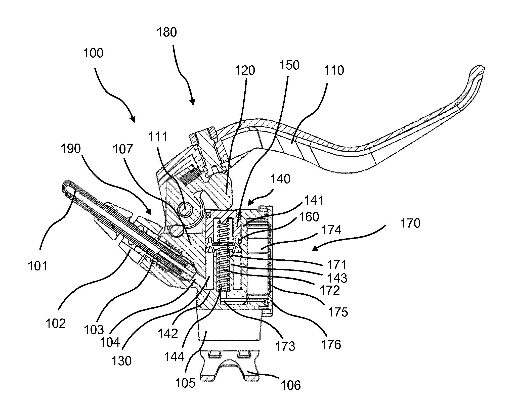
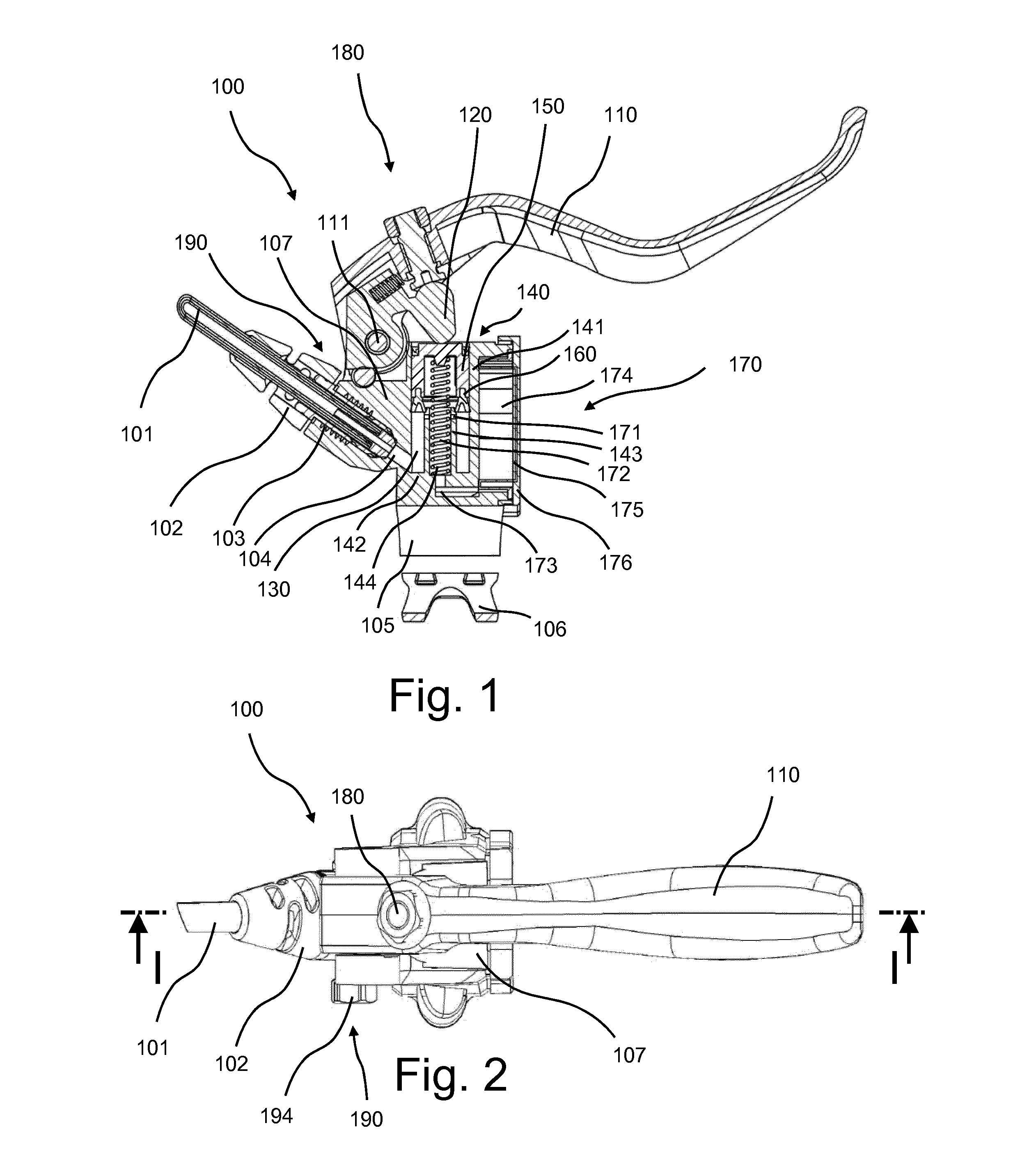
This patent describes a master cylinder for hydraulic brakes that has a gasket with two functions. The gasket serves as the primary gasket to interrupt the connection between the pressure chamber and the compensating chamber when the piston moves a certain distance. It also simultaneously seals the compensating chamber and the pressure chamber against the environment. This design allows for a shorter master cylinder structure in the direction of piston movement. Additionally, the patent describes a cover for the compensating chamber that serves as a secondary gasket and confines the path of the piston when the cover closes the compensating chamber. Overall, this design leads to improved efficiency and a more compact master cylinder.

Problems solved by technology

The known master cylinders have the drawback that they are made so as to have a relatively elongated design along the cylinder axis, which is due to the necessity of providing both a primary gasket and a secondary gasket.
As a result, the master cylinder is relatively large and heavy.
Particularly in the case of radial mountings where the cylinder axis extends perpendicularly to the axis of the handlebar and / or of inclined radial mountings in which the cylinder axis extends at an angle of less than 90 degrees, this yields a relatively large installation space and, thus, results in a relatively large distance between the handlebar and the center of rotation about which the lever of the brake fitting rotates when the master cylinder is actuated.

Method used


Image

  • Master Cylinder Device for a Hydraulic Disk Brake
  • Master Cylinder Device for a Hydraulic Disk Brake
  • Master Cylinder Device for a Hydraulic Disk Brake

Examples


Embodiment Construction

[0430]As required, detailed embodiments of the systems and methods are disclosed herein; however, it is to be understood that the disclosed embodiments are merely exemplary of the systems and methods, which can be embodied in various forms. Therefore, specific structural and functional details disclosed herein are not to be interpreted as limiting, but merely as a basis for the claims and as a representative basis for teaching one skilled in the art to variously employ the systems and methods in virtually any appropriately detailed structure. Further, the terms and phrases used herein are not intended to be limiting; but rather, to provide an understandable description of the systems and methods. While the specification concludes with claims defining the features of the systems and methods that are regarded as novel, it is believed that the systems and methods will be better understood from a consideration of the following description in conjunction with the drawing figures, in whic...


PUM


Abstract

A master cylinder for a hydraulic brake comprises a compensating chamber, a cylinder in which a piston is movably disposed, a pressure chamber disposed in the cylinder and connected to the compensating chamber through at least one connecting opening, and a gasket for interrupting the connection between the pressure chamber and the compensating chamber. The gasket seals the compensating chamber and the pressure chamber against the environment.

Description

CROSS-REFERENCE TO RELATED APPLICATIONS[0001]This is a continuing application, under 35 U.S.C. §120, of copending international application No. PCT / EP2014 / 050946, filed Jan. 17, 2014, which designated the United States and was not published in English; this application also claims the priority, under 35 U.S.C. §119, of German Patent Application Nos. 10 2013 200 824.4, filed Jan. 18, 2013; the prior applications are herewith incorporated by reference in their entirety.STATEMENT REGARDING FEDERALLY SPONSORED RESEARCH OR DEVELOPMENT[0002]Not ApplicableFIELD OF THE INVENTION[0003]The present systems and methods lies in the field of brakes. The present disclosure relates to a master cylinder for a hydraulic disk brake and / or a hydraulic disk brake including such a master cylinder, in particular, for handlebar-steered vehicles and / or bicycles and / or motorbikes.BACKGROUND OF THE INVENTION[0004]The known master cylinders for hydraulic disk brakes usually contain a compensating chamber for h...

Claims


Application Information

Patent Timeline
Patent Type & Authority Applications(United States)
IPC IPC(8): B62L3/02B60T11/236B60T11/22B60T11/16
CPCB62L3/023B60T11/22B60T11/236B60T11/165B60T7/102B60T11/16B60T11/228B60T11/232B62K23/06
Inventor RUOPP, MICHAEL
Owner GUSTAV MAGENWIRTH GMBH & CO KG
Learn More