Low-Turbulence Impeller for a Fluid Pump

a centrifugal fluid pump and impeller technology, which is applied in the direction of liquid fuel engines, machines/engines, reaction engines, etc., can solve the problems of easy damage to blades, and more severe cavitation corrosion, so as to promote fluid-draining efficiency, reduce energy consumption, and eliminate cavitation corrosion of fluids

Inactive Publication Date: 2015-11-26
YANG YUNG SHO
View PDF6 Cites 7 Cited by
  • Summary
  • Abstract
  • Description
  • Claims
  • Application Information

AI Technical Summary

Benefits of technology

[0007]The main objective of the present invention is to provide a low-turbulence impeller for a fluid pump that can eliminate cavitation corrosion of the fluid to reduce energy consumption and promote fluid-draining efficiency.

Problems solved by technology

Thus, the fluid will flow inversely due to negative pressures produced by the vortexes V. Further, cavitation corrosion of the fluid easily occurs and damages the blades 13.
When the rotational velocity of the pump impeller 1 is increased, the cavitation corrosion might be more severe.
As the conventional pump impeller 1 could not increase the rotational velocity in operating condition, the fluid-draining efficiency of the pump impeller 1 is insufficient.

Method used


Image

  • Low-Turbulence Impeller for a Fluid Pump
  • Low-Turbulence Impeller for a Fluid Pump
  • Low-Turbulence Impeller for a Fluid Pump

Examples


Embodiment Construction

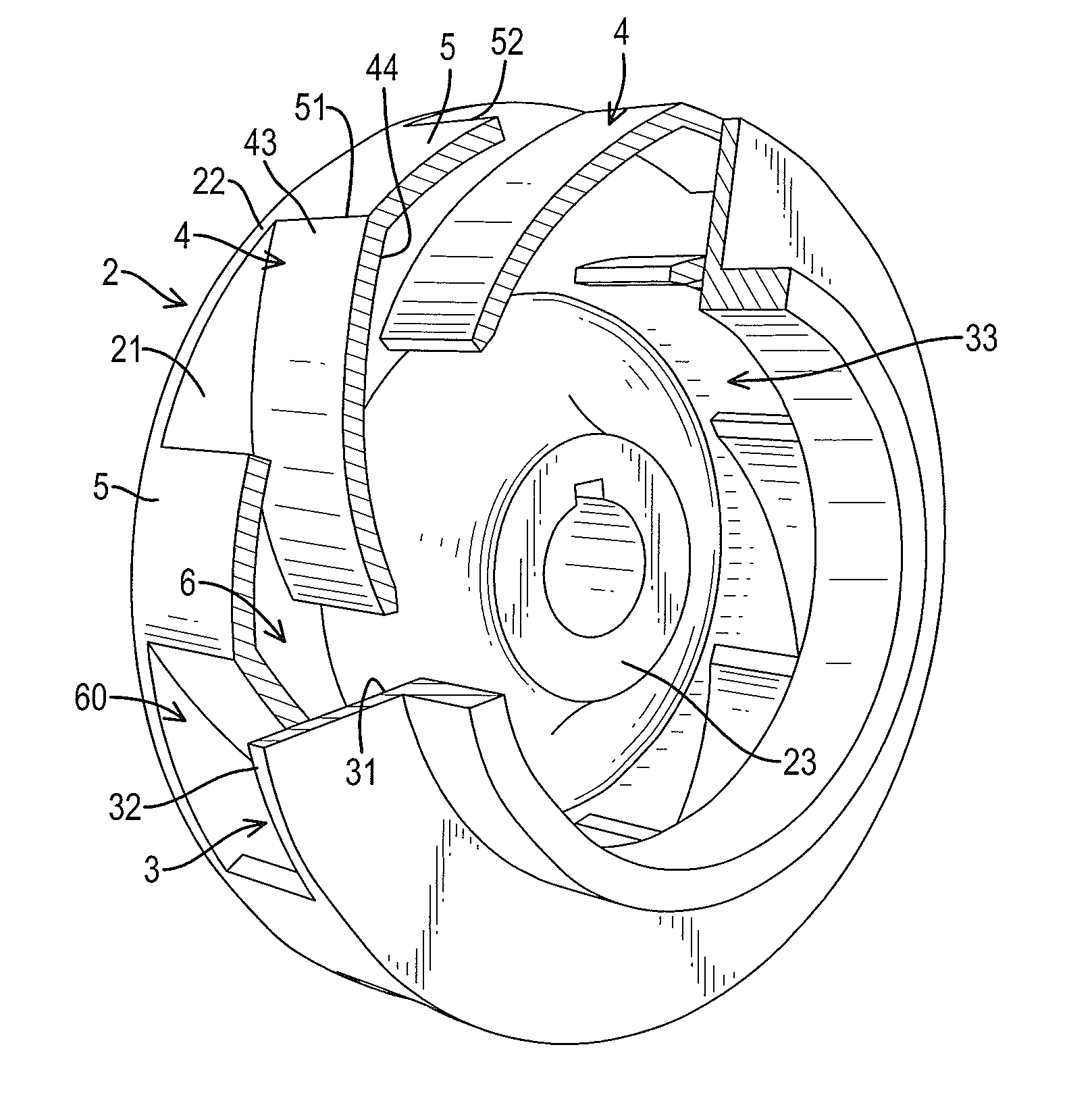
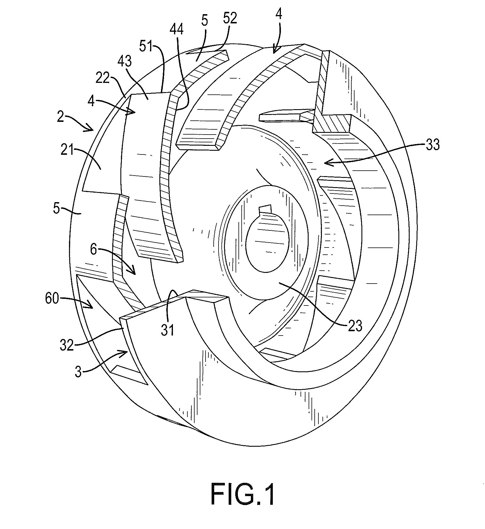
[0020]With reference to FIG. 1, a first preferred embodiment of a low-turbulence impeller for a fluid pump in accordance with the present invention is mounted in a casing of a centrifugal pump (not shown in figures). The centrifugal pump rotates the low-turbulence impeller.

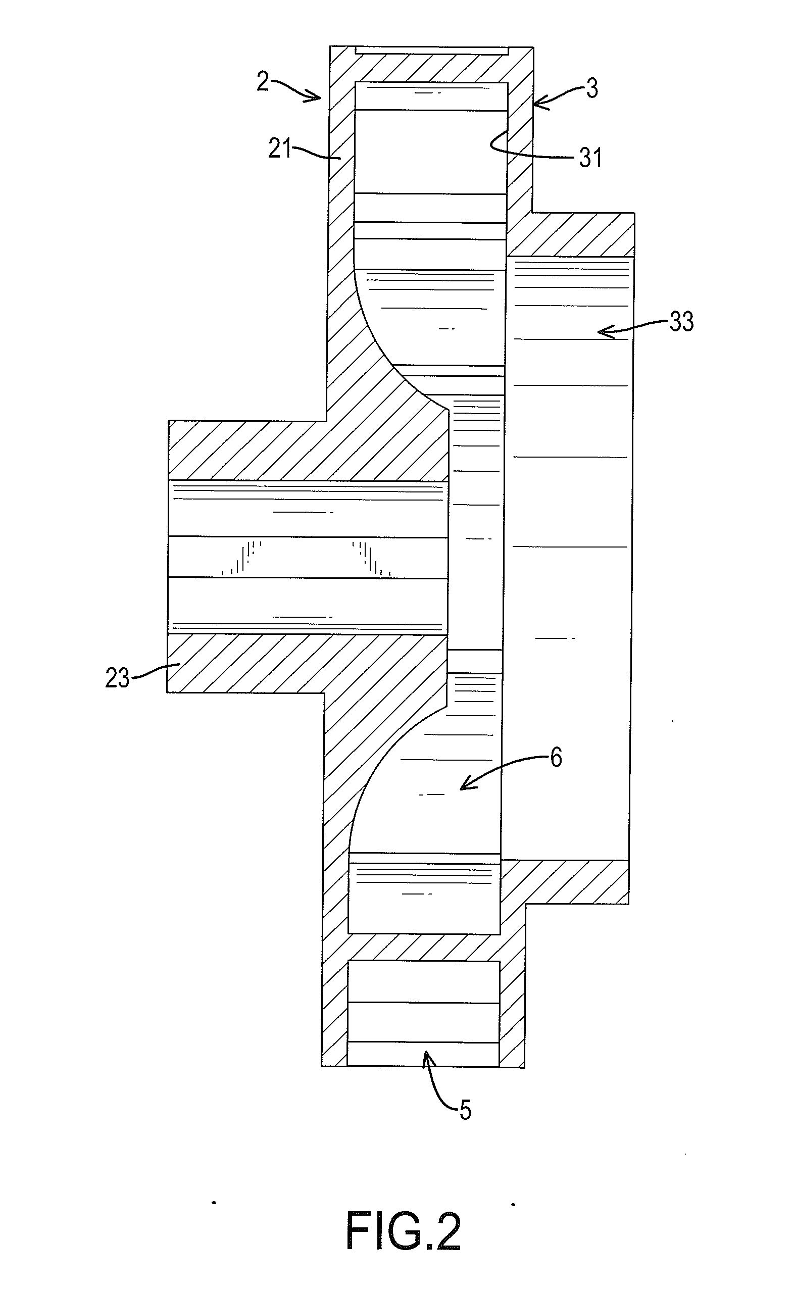
[0021]With reference to FIGS. 1 to 3, the low-turbulence impeller for a fluid pump comprises a first base wall 2, a second base wall 3, multiple guiding blades 4, multiple back-up plates 5, and multiple runners 6.

[0022]The first base wall 2 is circular and has a first inner surface 21, a first periphery 22, and a coupling portion 23. The coupling portion 23 is connected to a transmission shaft of a motor and is rotated by the motor. The second base wall 3 is spaced apart from and parallel to the first base wall 2. The second base wall 3 is circular and has a second inner surface 31 facing the first inner surface 21, a second periphery 32, and an inlet 33. The inlet 33 is formed through the second base wall 2 to al...


PUM


Abstract

A low-turbulence impeller for a fluid pump comprises a first base wall, a second base wall, multiple guiding blades, multiple back-up plates, and multiple runners. The second base wall has an inlet formed through the second base wall. Each one of the runners is formed between two adjacent guiding blades. Each runner has an outlet formed between two adjacent back-up plates. Each runner has a laminar zone communicating with a corresponding outlet and a turbulent zone aligning with the corresponding back-up plate. The fluid can only be flowed out of the outlet from the laminar zone, such that the fluid through the outlet of each runner is in low-turbulence condition. The phenomenon of inverse flow caused by negative pressures and the cavitation corrosion is greatly reduced. The rotational velocity of the low-turbulence impeller is enhanced to promote the fluid-draining efficiency.

Description

BACKGROUND OF THE INVENTION[0001]1. Field of the Invention[0002]The present invention relates to a pump impeller, especially a low-turbulence impeller for a centrifugal fluid pump.[0003]2. Description of the Prior Arts[0004]With reference to FIGS. 8 and 9, a conventional centrifugal pump impeller 1 has a first base wall 11, a second base wall 12 spaced apart from the first base wall 11, multiple blades 13 mounted between the first base wall 11 and the second base wall 12, and multiple runners 14. The second base wall 12 has an inlet 121 formed in a center of the second base wall 12. The blades 13 are curved and are spaced apart from each other. Each blade 13 has a first blade surface 131 and a second blade surface 132. Each one of the runners 14 is formed between a first blade surface 131 and a second blade surface 132 of two adjacent blades 13 for the flowing of fluid. A width of each blade 13 is constant. A width of each runner 14 is gradually increased from an interior to a perip...

Claims


Application Information

Patent Timeline
Patent Type & Authority Applications(United States)
IPC IPC(8): F01D5/14
CPCF01D5/141F04D29/2272F04D29/242F04D29/669F05D2240/304
Inventor YANG, YUNG-SHO
Owner YANG YUNG SHO
Why Eureka
Try Eureka