Ball valve controlling cavitation

A technology of ball valve and cavitation, which is applied to valve details, valve devices, cocks including cut-off devices, etc., can solve problems such as cavitation, achieve the effects of improving the working environment, eliminating cavitation, and facilitating assembly

Pending Publication Date: 2017-12-08
CHANGZHENG ENG +1
View PDF0 Cites 2 Cited by
  • Summary
  • Abstract
  • Description
  • Claims
  • Application Information

AI Technical Summary

Problems solved by technology

[0004] The invention provides a ball valve for controlling cavitation, which is used to solve the problem that the existing ball valve is prone to cavitation. The invention can reduce the cavitation phenomenon, help to reduce the noise and vibration generated by the fluid, and prolong the service life of the valve.

Method used


Image

  • Ball valve controlling cavitation
  • Ball valve controlling cavitation
  • Ball valve controlling cavitation

Examples


Embodiment Construction

[0029] In order to make the technical problems, technical solutions and advantages to be solved by the present invention clearer, the following will describe in detail with reference to the drawings and specific embodiments.

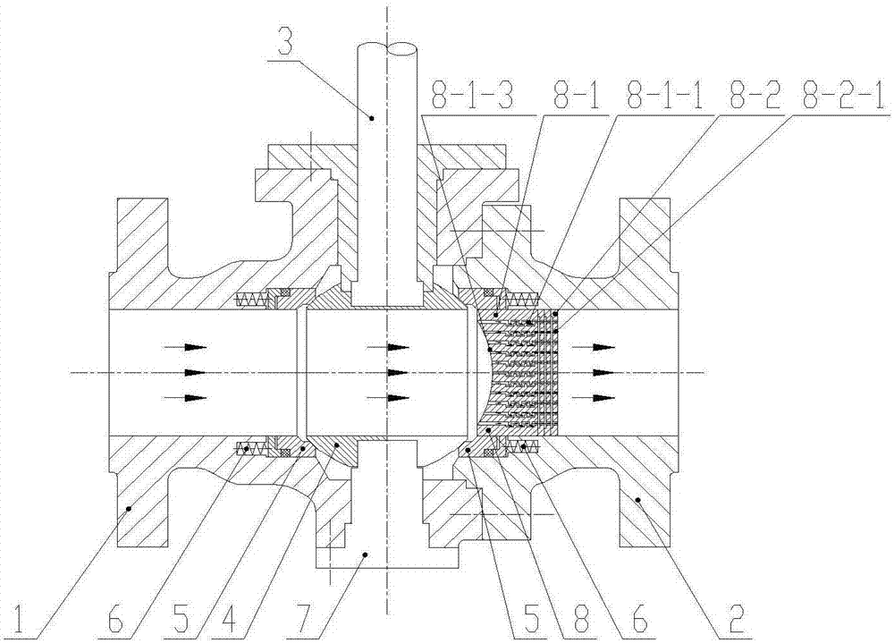
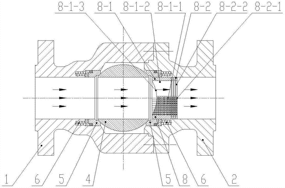
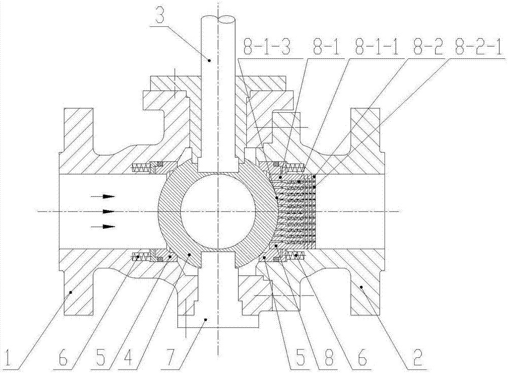
[0030] figure 1 It is a schematic diagram of the front cross-sectional structure of a ball valve for controlling cavitation in the present invention in a fully open state, figure 2 It is a schematic diagram of the cross-sectional structure of a ball valve for controlling cavitation of the present invention in a fully open state, image 3 It is a schematic diagram of the front sectional structure of a ball valve for controlling cavitation in the fully closed state of the present invention, Figure 4 It is a schematic diagram of the cross-sectional structure of a ball valve for controlling cavitation of the present invention in a fully closed state, Figure 5 It is a schematic diagram of the cross-sectional structure of a cavitation-controlling ball val...


PUM


Abstract

The invention provides a ball valve controlling cavitation and belongs to the technical field of pipeline control. The ball valve controlling the cavitation is used for solving the problem that an existing ball valve is prone to generating the cavitation. The ball valve controlling the cavitation comprises a valve body composed of a first valve body portion and a second valve body portion, a sphere, a valve rod, valve seats, springs and a fixing shaft, wherein the sphere, the valve rod, the valve seats, the springs and the fixing shaft are located between the first valve body portion and the second valve body portion. The fixing shaft is located on the lower side of the sphere and used for supporting the sphere. The valve rod is connected with the sphere and used for driving the sphere to rotate. Spherical surface seal is formed by the sphere and the valve seats on the left and right sides. The springs are arranged on the outer sides of the valve seats and used for pressing the valve seats to the sphere. The ball valve further comprises a valve element which is arranged on an outlet flow channel of the sphere in a tightly attached manner. The valve element is provided with a channel extending in the direction of a ball valve flow channel. The ball valve controlling the cavitation can effectively restrain generation of the cavitation and is beneficial for lowering of noise and vibration generated by fluid.

Description

technical field [0001] The invention relates to the technical field of pipeline control, in particular to a ball valve for controlling cavitation. Background technique [0002] Ball valves are widely used in coal chemical, petrochemical, iron and steel, metallurgy and other industries due to their advantages such as small fluid resistance, large flow capacity, fast switching, good sealing performance, long life, and convenient air control and electric control. [0003] However, the ball valve has the characteristics of large flow capacity and rapid switching. Especially during the opening and closing process of the valve, due to the large pressure difference on both sides of the valve and the high flow rate of the fluid medium, it is very easy to cause cavitation. When the speed of the ball valve passes through the flow channel of the ball valve, due to the decrease of the pressure of the liquid fluid, the gas is precipitated to generate bubbles. When the pressure on the bub...

Claims


Application Information

Patent Timeline
Patent Type & Authority Applications(China)
IPC IPC(8): F16K5/06F16K5/08F16K47/04
CPCF16K5/0605F16K5/08F16K47/045
Inventor 赵海燕刘际周岩王松刘成钢
Owner CHANGZHENG ENG
Why Eureka
Try Eureka