Labyrinth adjusting valve

A control valve and labyrinth technology, applied in the field of labyrinth control valve, can solve the problems of reducing outlet flow rate, cavitation, strong vibration, etc., and achieve the effect of reducing outlet flow rate, solving cavitation, and reducing medium flow rate

Pending Publication Date: 2016-07-06
CHANGZHENG ENG +1
View PDF6 Cites 5 Cited by
  • Summary
  • Abstract
  • Description
  • Claims
  • Application Information

AI Technical Summary

Problems solved by technology

[0005] In order to overcome the defects of the prior art, the object of the present invention is to propose a labyrinth control valve, through the combined design of the labyrinth sleeve components, a three-dimensional flow channel is formed to reduce the The purpose of the outlet flow rate, and to solve the problems of easy cavitation, high noise and strong vibration when the medium passes through the regulating valve

Method used


Image

  • Labyrinth adjusting valve
  • Labyrinth adjusting valve
  • Labyrinth adjusting valve

Examples


Embodiment Construction

[0026] The technical solutions in the embodiments of the present invention will be clearly and completely described below in conjunction with the embodiments of the present invention and the accompanying drawings. Apparently, the described embodiments are only some of the embodiments of the present invention, not all of them. Based on the embodiments of the present invention, all other embodiments obtained by persons of ordinary skill in the art without making creative efforts belong to the protection scope of the present invention.

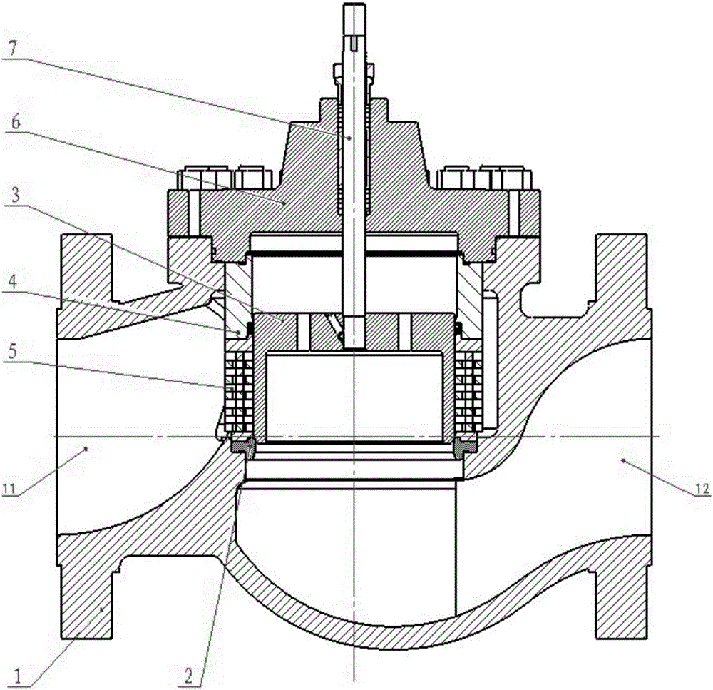
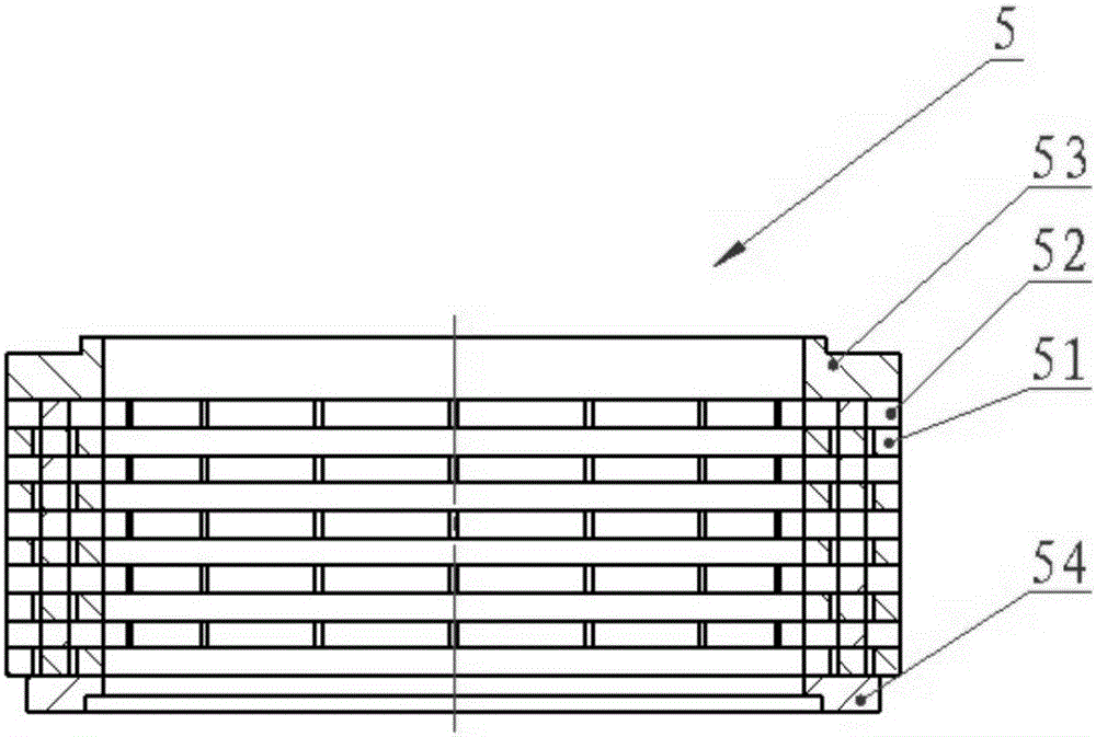
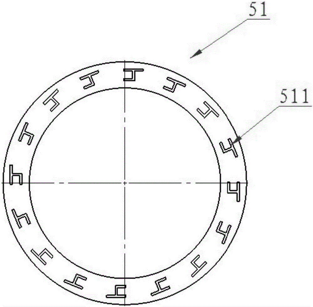
[0027] The embodiment of the present invention provides a labyrinth regulating valve, such as figure 1 As shown, it includes: valve body 1, valve seat 2, valve core 3, balance seat 4, labyrinth sleeve assembly 5, valve cover 6, valve stem 7, valve body 1 is provided with a medium inlet 11 and a medium outlet 12, the valve The seat 2 is located at the medium outlet 12, the labyrinth sleeve assembly 5 is placed between the valve seat 2 and the bala...


PUM


Abstract

The invention discloses a pipeline control valve and particularly discloses a labyrinth adjusting valve, comprising a valve body, a valve seat, a spool, a labyrinth sleeve assembly, a bonnet and a valve stem. The valve body is provided with a medium inlet and a medium outlet, the labyrinth sleeve assembly comprises one or more labyrinth plates, one or more guide plates, an upper plate and a lower plate, and the labyrinth plates and the guide plates are located between the upper plate and the lower plate; each labyrinth plate has a flow passage, and/or each guide plate has a flow passage. In conclusion, the labyrinth adjusting valve provided herein can reduce medium flow speed in a medium flowing process, thus reducing the adjusting valve outlet flow speed under high temperature, great pressure difference and high flow speed and solving the problem that cavitation, high noise and severe vibration are caused when a medium passes through the adjusting valve.

Description

technical field [0001] The invention relates to a pipeline control valve, in particular to a labyrinth regulating valve used to control fluid with high pressure difference. Background technique [0002] Regulating valve is a commonly used valve, the main function is to adjust the pressure, flow, temperature and other parameters of the medium. The main structure of the regulating valve is composed of valve body, valve seat, valve core and valve cover. The valve seat is installed in the valve body. The valve seat is a hollow cylindrical structure. The valve core is located in the valve seat. Opening or closing of media channels. [0003] Ordinary regulating valve, when the medium flows to the valve core, due to the throttling effect of the valve core and the valve seat, a necking phenomenon occurs, so the speed will increase rapidly, and the pressure will decrease rapidly. In this case, the medium vaporizes , forming bubbles. When the medium flows through the constriction f...

Claims


Application Information

Patent Timeline
Patent Type & Authority Applications(China)
IPC IPC(8): F16K47/08F16K3/26
CPCF16K3/267F16K47/08
Inventor 颜震李峰汪欢盖玉龙
Owner CHANGZHENG ENG
Why Eureka
Try Eureka