
Marine propeller drive

a propeller and propeller hub technology, applied in the direction of marine propulsion, propulsive elements, vessel construction, etc., can solve the problems of increasing the diameter of the propeller by significantly more than 25%, reducing the efficiency of the propeller, and reducing the risk of cavitation. , the effect of reducing the risk of cavitation

Active Publication Date: 2013-05-21
VOLVO PENTA AB
View PDF7 Cites 2 Cited by
  • Summary
  • Abstract
  • Description
  • Claims
  • Application Information

AI Technical Summary

Benefits of technology

The present invention is a new design for a propeller drive that improves efficiency and reduces negative effects such as turbulence, cavitation, and erosion. It achieves these improvements by using a straight transition between gearbox and propeller, which results in a more even velocity profile and higher absolute pressure at the propeller hub, minimizing the risks of cavitation. Additionally, the design reduces turbulence intensity around the propeller hub and root parts of the propeller blades, eliminating cavitation erosion.

Problems solved by technology

The problem thus arises that the gearbox must be dimensioned so large, for reasons related to power or stability to stress, that the diameter of the propeller hub, in the case of a straight transition between the gearbox and the propeller hub, must exceed the diameter of the propeller by significantly more than 25%.
The problem has therefore been considered to be unsolvable in general, since a conventional straight or slightly curved transition cone has turned out to result in undesirable cavitation around the propeller hub because dissolving takes place already at the first, front end of the transition cone, which is located upstream.
The cavitation around the propeller hub also entails a big problem with cavitation erosion of the propeller blades against the root parts adjacent to the hub, loss of efficiency, with the consequence of unfavorable flow behavior in the cavitation zone around the root parts, and pressure impulses at the entrance end of the hub.
As a consequence of the fact that problems are encountered with an enlarged gearbox in comparison with the diameter of the propeller both if a larger hub diameter is selected (leading to a drop in the degree of efficiency of the propeller drops) and if a thin propeller hub is retained in conjunction with a conventional transition cone (leading to cavitation erosion and loss of efficiency), a convention has developed among designers that the gearbox should generally not be dimensioned larger than 25% of the propeller diameter.

Method used


Image

  • Marine propeller drive
  • Marine propeller drive
  • Marine propeller drive

Examples


Embodiment Construction

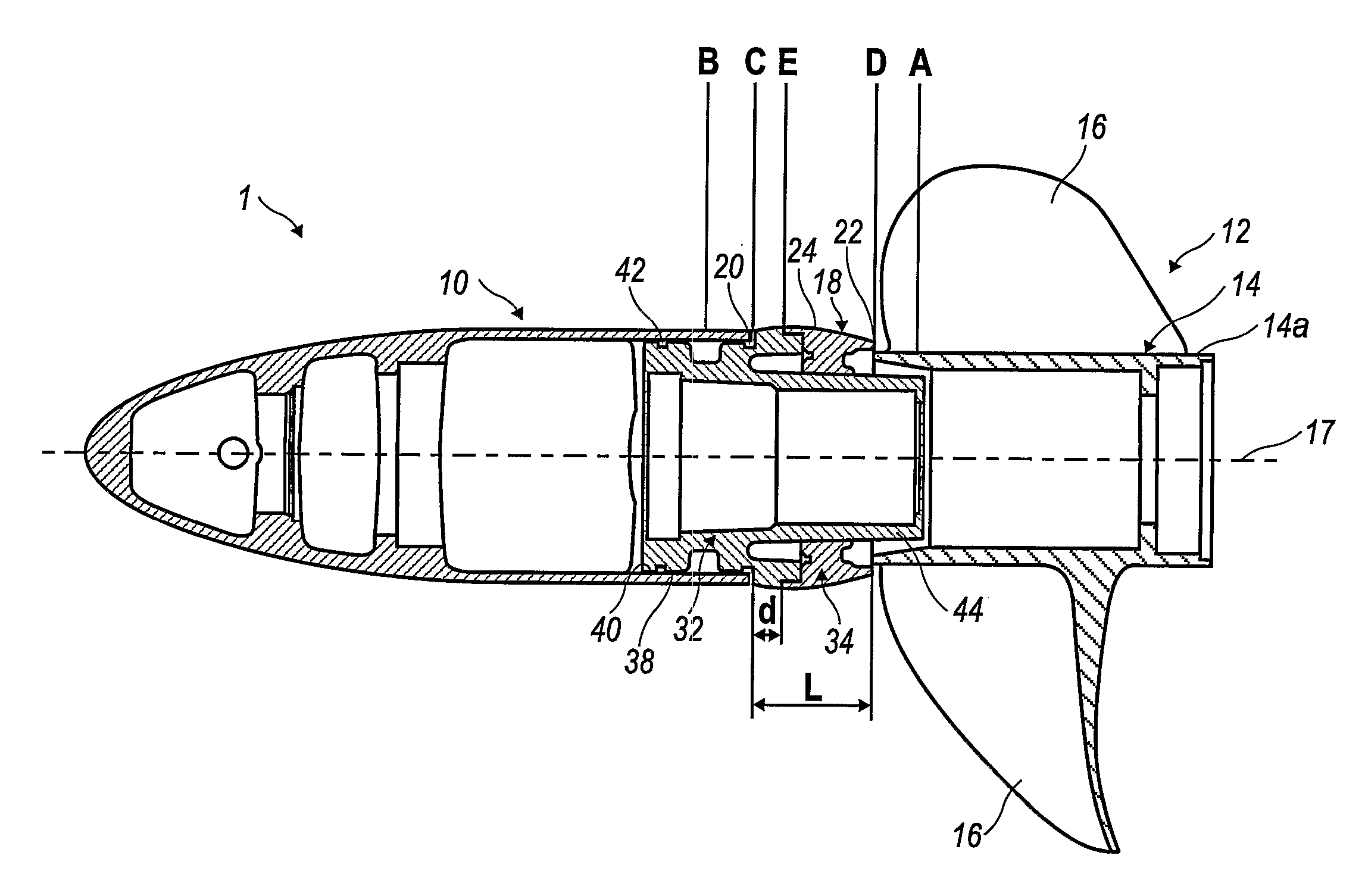
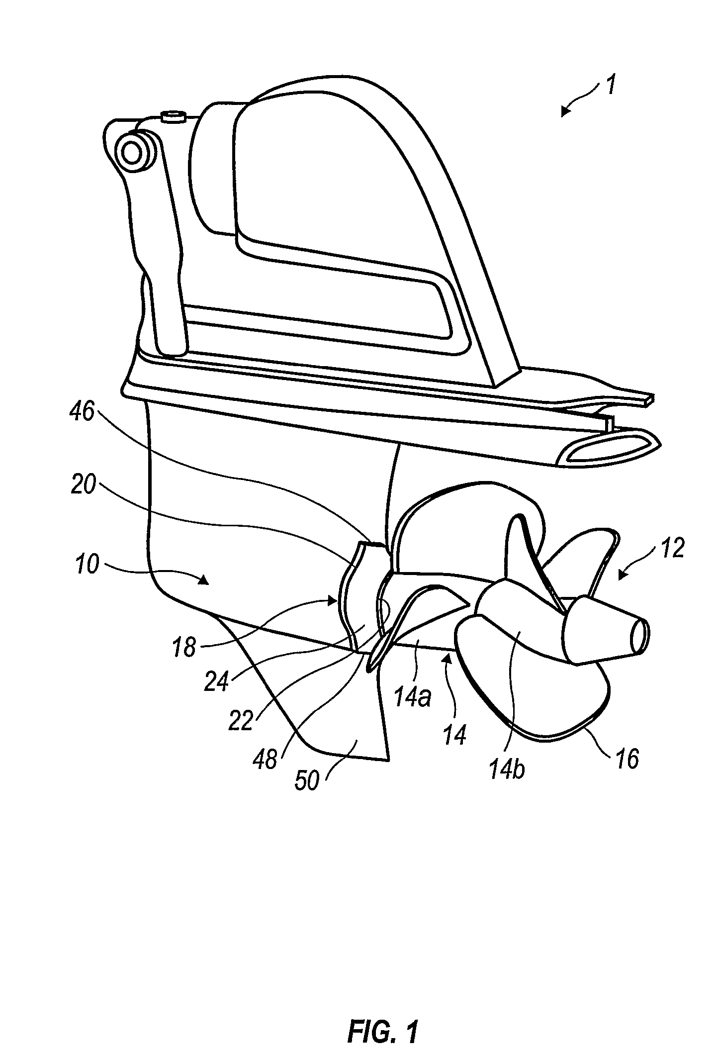
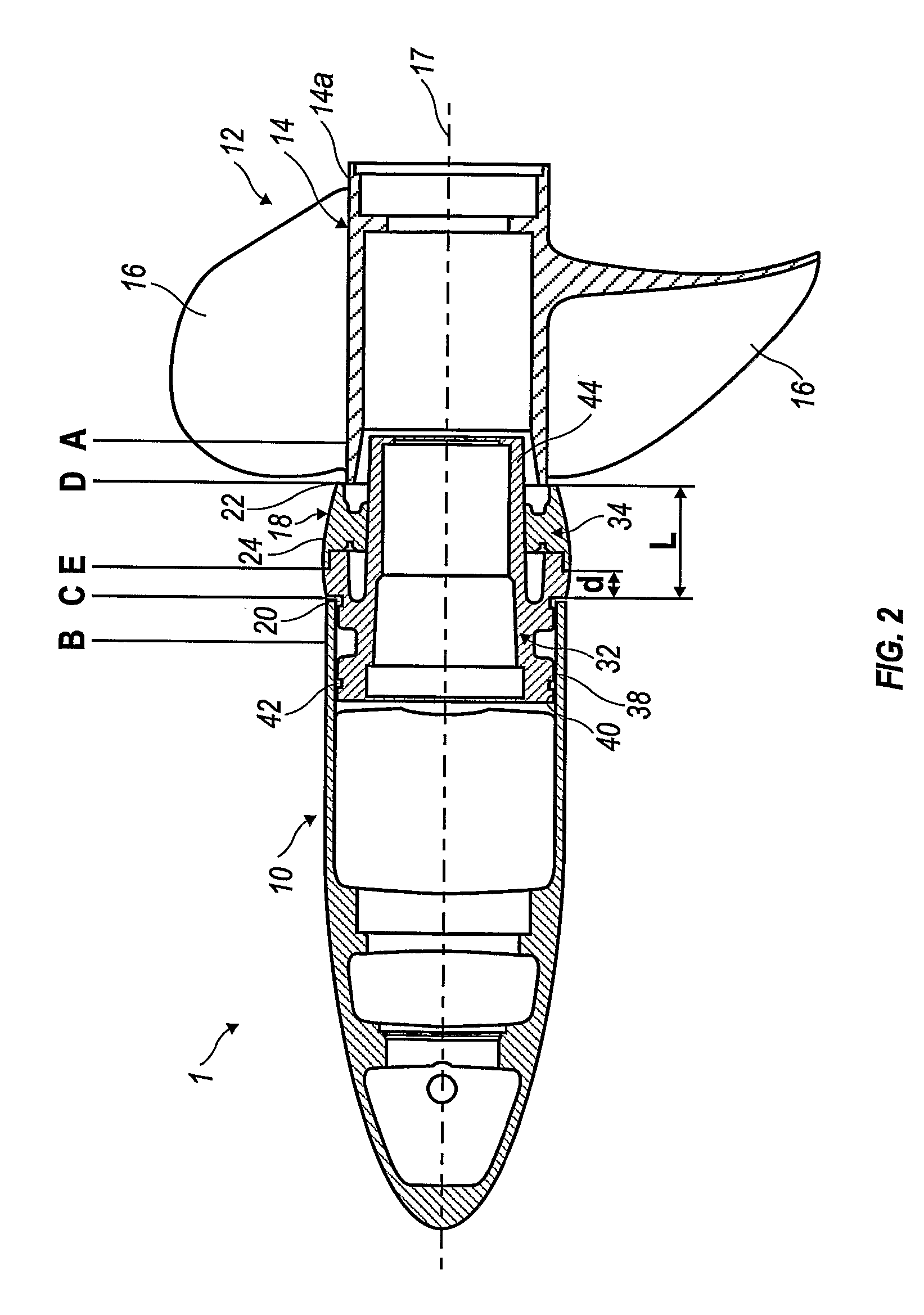
[0021]A marine propeller drive 1 for boats is shown in FIG. 1 that is configured according to the present invention. The propeller drive 1 in the embodiment shown is mounted on the square stern of the boat, but it can alternatively also be of the outboard type (not shown). The propeller drive is envisioned primarily for fast boats, i.e. boats with a top speed exceeding about 20 knots, but it can also be used with slower boats.

[0022]The propeller drive 1 includes a lower gearbox 10, which contains part of a motor transmission (not shown). The motor transmission is connected in a known manner to a motor in a boat. Neither the motor nor the boat is shown in the figures since these components are well known to those persons skilled in these arts. In the embodiment shown, the gearbox 10 has a shape similar to that of a wing profile. The propeller drive 1 also includes a counter-rotating impelling double propeller 12, but in an alternative embodiment (not shown), it can also be provided w...


PUM


Abstract

A propeller drive for boats features a transition cone between the gearbox housing and the propeller hub(s). The propeller hub (that is closest to the gearbox housing) is smaller in cross-sectional dimension than the gearbox housing. The dimension of the front end of the transition cone corresponds to the cross-sectional dimension of the gearbox housing, and the dimension of the rear end of the transition cone corresponds to the cross-section dimension of the (closest) propeller hub. The transition cone has a bulging shoulder between the front and rear ends, the largest peripheral cross-sectional dimension of which is greater than the cross-sectional dimension of the front of the transition cone.

Description

CROSS-REFERENCE TO RELATED APPLICATIONS[0001]The present application is a continuation patent application of International Application No. PCT / SE2004 / 000601 filed 20 Apr. 2004 which is published in English pursuant to Article 21(2) of the Patent Cooperation Treaty and which claims priority to Swedish Application No. 0301644-1 filed 5 Jun. 2003. Said applications are expressly incorporated herein by reference in their entireties.FIELD OF THE INVENTION[0002]The present invention relates to a marine propeller drive for boats. The propeller drive can be mounted on the square stern of a boat or be of the outboard type, and it is provided with a simple impelling propeller or a counter-rotating impelling double propeller.BACKGROUND OF THE INVENTION[0003]A propeller drive of the above-mentioned type is constructed to meet the demands of the market for much faster boats with much larger and more powerful motors. In order to maintain or increase the operating life of the propeller drive with ...

Claims


Application Information

Patent Timeline
Patent Type & Authority Patents(United States)
IPC IPC(8): B63H20/32B63H1/20B63H5/125
CPCB63H1/20B63H20/32B63H5/125B63H2005/1256
Inventor JONSSON, KAREHEDLUND, BENNY
Owner VOLVO PENTA AB
Learn More