
Subsea power transmission

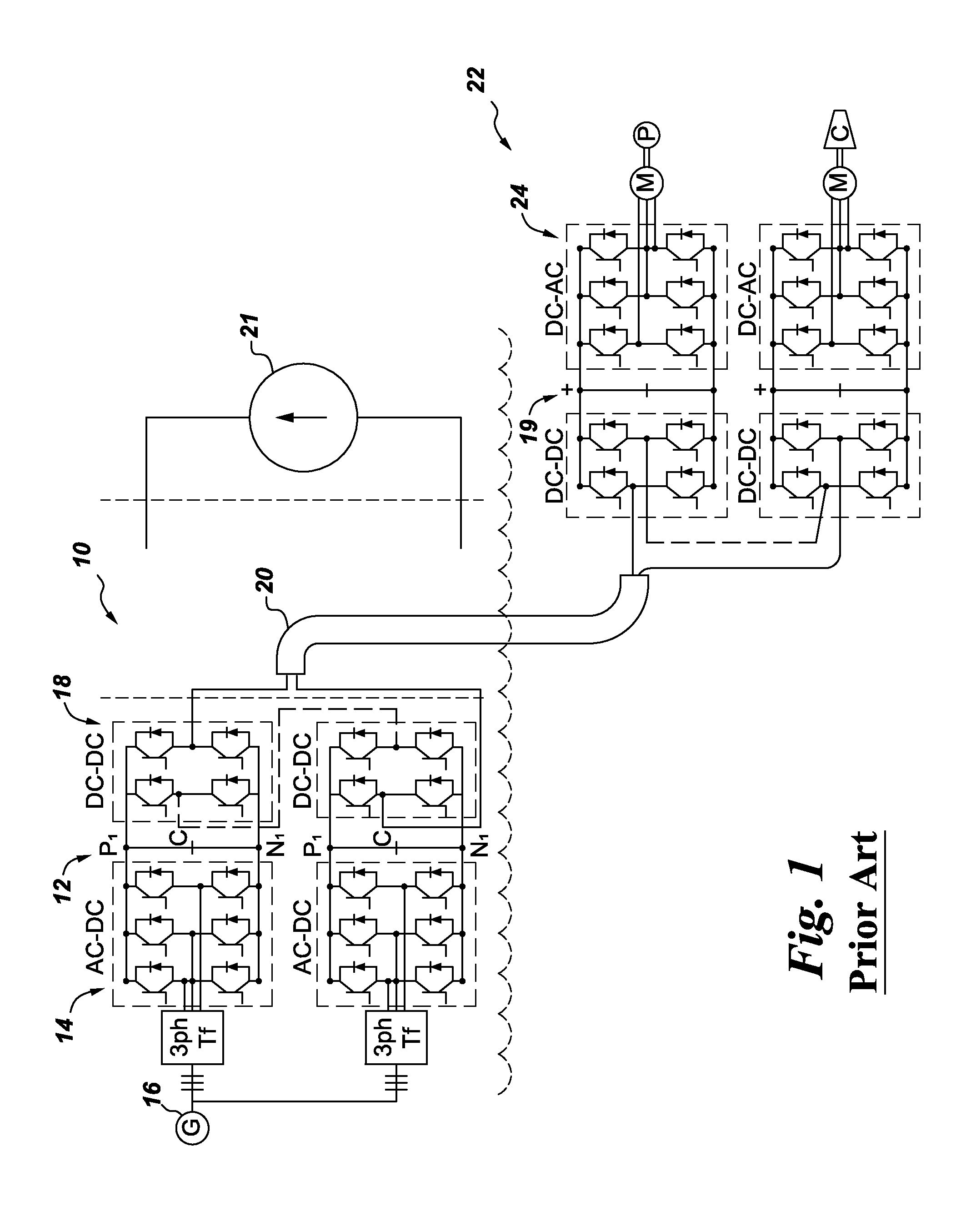
a sub-sea power transmission and sub-sea technology, applied in the direction of electric variable regulation, process and machine control, instruments, etc., can solve the problems of high cable loss, difficult to achieve sub-sea distribution, and high cost of ac power transmission

Inactive Publication Date: 2015-11-26
GENERAL ELECTRIC CO
View PDF0 Cites 6 Cited by
  • Summary
  • Abstract
  • Description
  • Claims
  • Application Information

AI Technical Summary

Benefits of technology

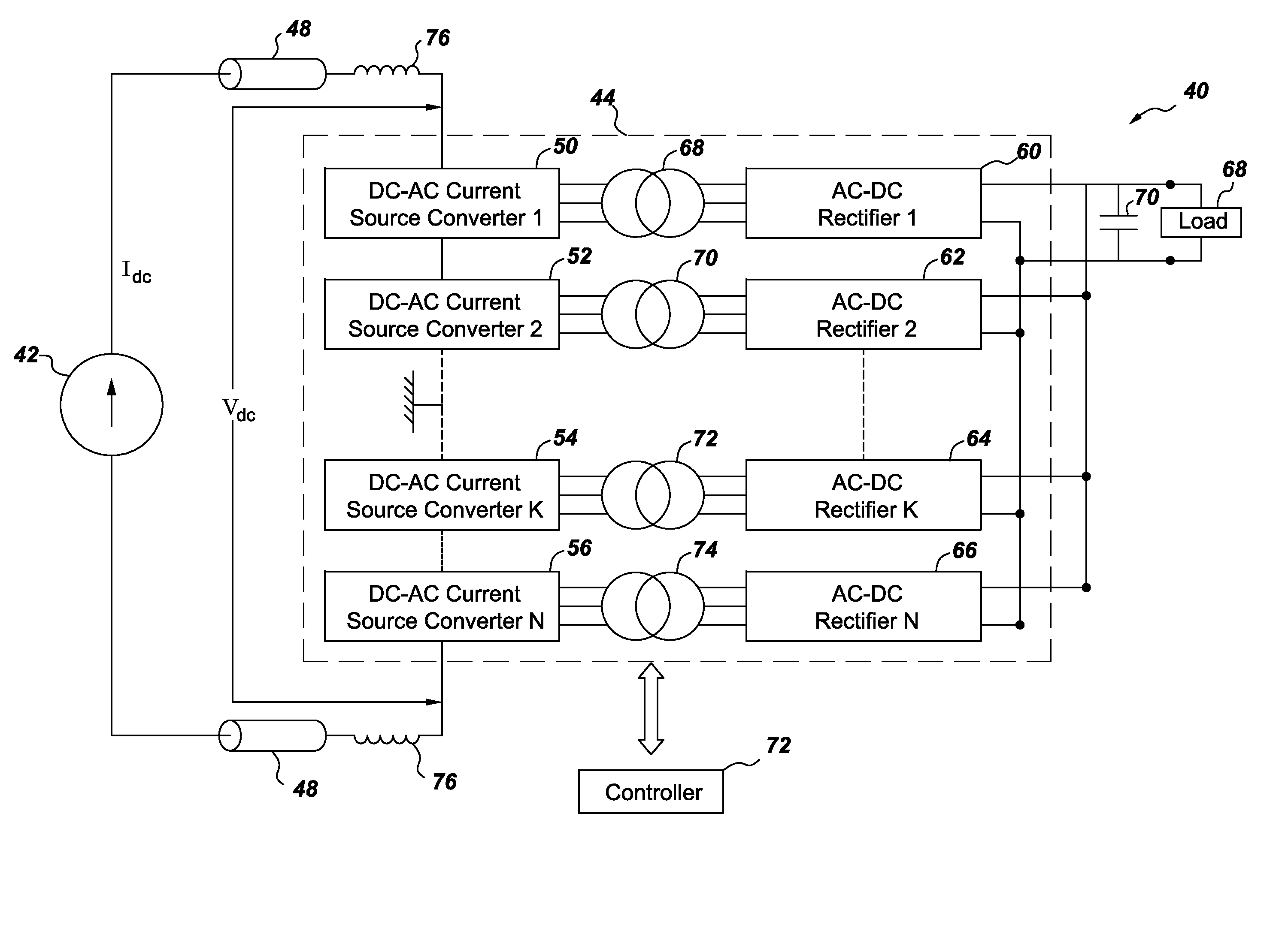
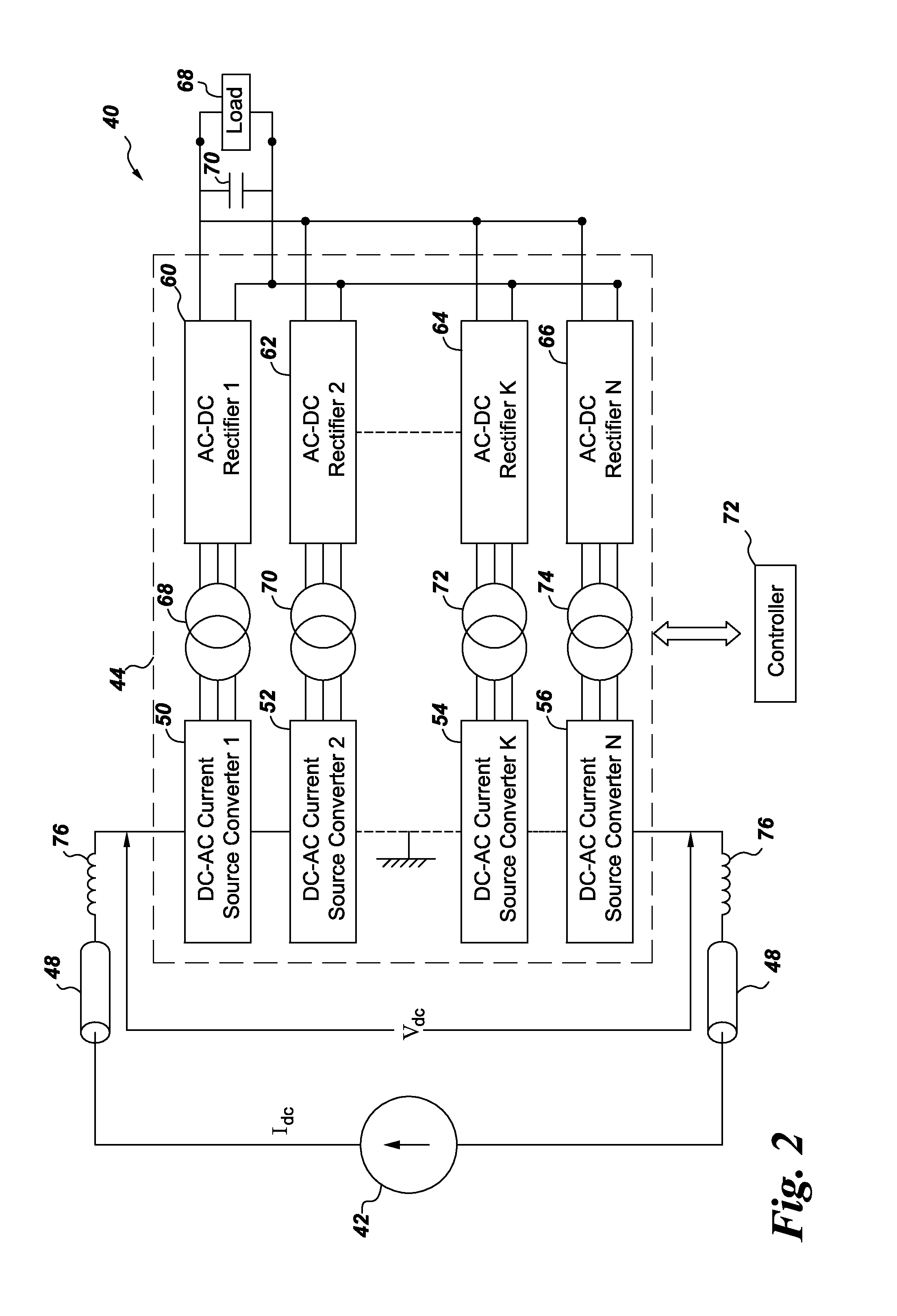
This patent describes a power transmission and distribution system that uses reverse blocking fully controllable switches to efficiently transfer power from a current source to a receiving side with multiple loads. The system includes a plurality of DC-AC current source converters and AC-DC rectifiers connected in series and parallel, allowing for the distribution of power at subsea locations. The technical effect of this invention is to provide a more efficient and flexible system for transmitting power in DC and AC forms to subsea loads.

Problems solved by technology

The transmission of high power over a distance of more than 100 km and distributing the power sub-sea is a very challenging problem.
AC power transmission, although mature, provides technical challenges for applications where bulk power is transmitted over long cables.
Because the cable must carry this charging current in addition to the useful load current, the cable losses are high; the cables are over-rated and expensive.
Large reactive power requirements may trigger power system stability issues.
However, LCC converters require significant amount of filters to supply for desired reactive power whereas VSC converters require large DC capacitors which affects reliability and maintenance.

Method used


Image

  • Subsea power transmission
  • Subsea power transmission
  • Subsea power transmission

Examples


Embodiment Construction

[0013]Unless defined otherwise, technical and scientific terms used herein have the same meaning as is commonly understood by one of ordinary skill in the art to which this disclosure belongs. The terms “first”, “second”, and the like, as used herein do not denote any order, quantity, or importance, but rather are used to distinguish one element from another. Also, the terms “a” and “an” do not denote a limitation of quantity, but rather denote the presence of at least one of the referenced items. The term “or” is meant to be inclusive and mean one, some, or all of the listed items. The use of “including,”“comprising” or “having” and variations thereof herein are meant to encompass the items listed thereafter and equivalents thereof as well as additional items. The terms “connected” and “coupled” are not restricted to physical or mechanical connections or couplings, and can include electrical connections or couplings, whether direct or indirect. Furthermore, the terms “circuit” and ...


PUM


Abstract

A power transmission and distribution system includes a supplying side having a current source and a receiving side. The receiving side includes a modular converter with plurality of direct current (DC)-alternating current (AC) current source converters connected in series with the current source and a plurality of AC-DC rectifiers connected in parallel to supply power to a multiplicity of loads. Each of the DC-AC current source converters supply power to a corresponding AC-DC rectifier and includes a plurality of reverse blocking fully controllable switches having bidirectional voltage blocking capability. Furthermore, a current from the current source flows in at least one reverse blocking fully controllable switch at any instant.

Description

BACKGROUND[0001]The invention relates generally to power transmission and more specifically to a system and method for transmitting electrical power to sub-sea electrical equipment.[0002]Sub-sea electrical equipment such as a sub-sea motor which drives a gas compressor has a higher nominal power rating (e. g., in the order of 10 or 15 MW). As such, sub-sea compression clusters may be required to transmit a total power in the order of 50 to 100 MW over a distance of 100 or 200 km. The transmission of high power over a distance of more than 100 km and distributing the power sub-sea is a very challenging problem. Such a transmission is done at high voltages to reduce losses. At the receiving sub-sea end, the voltage is stepped-down and then distributed to the individual loads. Distribution distances are typically much shorter than the transmission distance.[0003]Three phase alternating current (AC) power transmission and distribution is one way of transmitting power to subsea equipment...

Claims


Application Information

Patent Timeline
IPC IPC(8): H02J1/08H02M3/335
CPCH02J1/08Y10T307/406H02J2001/002H02M3/33576H02J3/36Y02E60/60H02J1/002
Inventor TENCA, PIERLUIGI
Owner GENERAL ELECTRIC CO
Learn More