
Methods and apparatus for determining a path in a communications network

a communication network and path technology, applied in the field of determining a path in a communications network, can solve the problems of additional equipment, no immediate benefit, and additional constraints, and achieve the effects of short permitted outage time, easy reroute, and convenient rerou

Inactive Publication Date: 2015-11-26
CIENA
View PDF6 Cites 4 Cited by
  • Summary
  • Abstract
  • Description
  • Claims
  • Application Information

AI Technical Summary

Benefits of technology

[0012]Preferably, the path setup request does not specify a protection technique. This allows the protection technique to be chosen by they network based on the user requirements (as specified in the path setup request) and the network information. Because this improves flexibility, this may well provide at least as good protection as the user expects but at lower network cost.
[0014]Other parameters passed with the path request may include resiliency, typically in terms of a maximum outage period and / or an outage occurrence rate per annum. These parameters allow the network to recognise a path which can easily be rerouted compared to a path (for example with a very short permitted outage time) which cannot easily be re-routed “on the fly”. Reduced flexibility and re-routing (as explained below) increases the cost of carrying the path since it may result in non-optimal use of the network for other paths.

Problems solved by technology

For analogue networks such as optical networks however, additional constraints must be taken into account.
Thus, additional equipment, especially regenerators, has been inserted into the network and gives no immediate benefit.
Furthermore, the network has little flexibility in how to provision the path.

Method used


Image

  • Methods and apparatus for determining a path in a communications network
  • Methods and apparatus for determining a path in a communications network
  • Methods and apparatus for determining a path in a communications network

Examples


Embodiment Construction

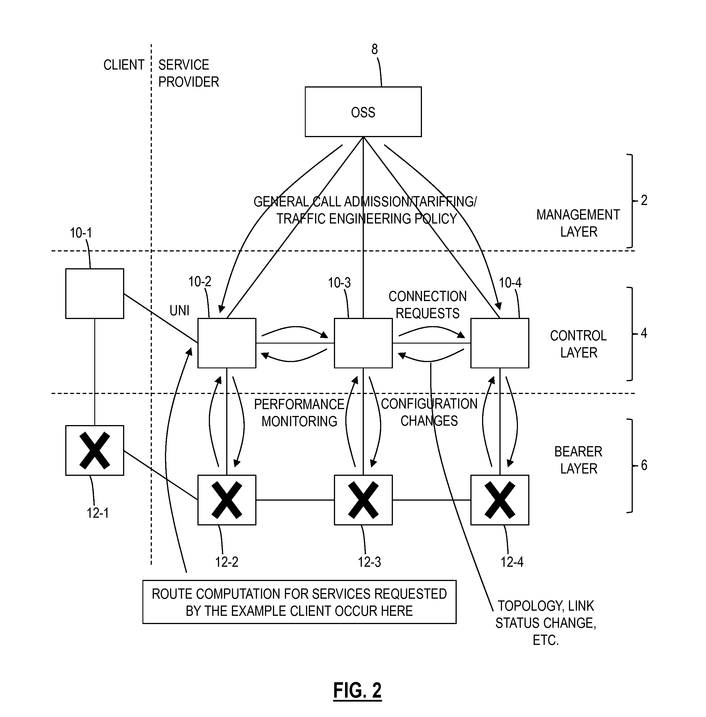
[0025]With reference to FIG. 2, a typical network may have a management layer 2, a control layer 4 and a bearer layer 6. It will be appreciated that the logical separation of the network into these layers is somewhat arbitrary and that in practice parts of the control layer may be distributed, for example, between the bearer layer and the management layer. Nevertheless, for ease of explanation, these functions will be considered to be separate layers in the description below.

[0026]The management layer 2 typically contains an operations support system (OSS) 8 which carries out the co-ordination network functions by providing overall policy information to nodal controllers 10-1 to 10-4 in the control layer, and other functions such as monitoring for faults and locating faults.

[0027]The control layer has a plurality of nodal controllers 10-1 to 10-4 which share information such as link topology updates, available resources and physical layer analogue optical parameters (in an optical n...


PUM


Abstract

A method for determining a path in an optical network, implemented by one or more controllers associated with a control layer, includes receiving a path request specifying start and end points, an associated bandwidth, and a longevity parameter providing an anticipated length during which the path is required; determining a route in the optical network through a routing algorithm executed by the controller, wherein the routing algorithm utilizes the start and end points, the associated bandwidth, and the longevity parameter to determine the path; and provisioning the path through a plurality of switches along the route.

Description

CROSS-REFERENCE TO RELATED APPLICATION(S)[0001]The present patent / application is a continuation of U.S. patent application Ser. No. 10 / 675,760 filed Sep. 30, 2003 and entitled “METHODS AND APPARATUS FOR DETERMINING A PATH IN A COMMUNICATIONS NETWORK,” the contents of which are incorporated by reference herein.FIELD OF THE INVENTION[0002]This invention relates to a method of determining a path in a communications network in response to a path setup request including parameters which specify characteristics relating to a service level requirement for the path, and to corresponding apparatus and software.BACKGROUND OF THE INVENTION[0003]When users wish to communicate across a communications network such as an optical network, it is necessary for a path to be provisioned through the network between the two desired end points at the user locations. Thus a typical first step in setting up a connection between the users would be to issue a path set up request to the control layer of the ne...

Claims


Application Information

Patent Timeline
Patent Type & Authority Applications(United States)
IPC IPC(8): H04Q11/00H04L12/721H04L12/727H04L12/725H04L45/121
CPCH04Q11/0066H04L45/30H04Q2011/0086H04L45/121H04Q2011/0073H04L45/70H04J14/0257H04J14/0271H04J14/0295H04L45/124H04L45/127H04L45/308H04B10/25
Inventor FRISKNEY, ROBERTDAVIS, FIONABAKER, NIGELPHILLIPS, CHRISTOPHERDONG, SONG
Owner CIENA
Learn More