Carrier aggregation management

Active Publication Date: 2015-11-26
VERIZON PATENT & LICENSING INC
View PDF9 Cites 28 Cited by
  • Summary
  • Abstract
  • Description
  • Claims
  • Application Information

AI Technical Summary

Problems solved by technology

The large number of mobile communication devi

Method used


Image

  • Carrier aggregation management
  • Carrier aggregation management
  • Carrier aggregation management

Examples


Embodiment Construction

[0011]The following detailed description refers to the accompanying drawings. The same reference numbers in different drawings identify the same or similar elements.

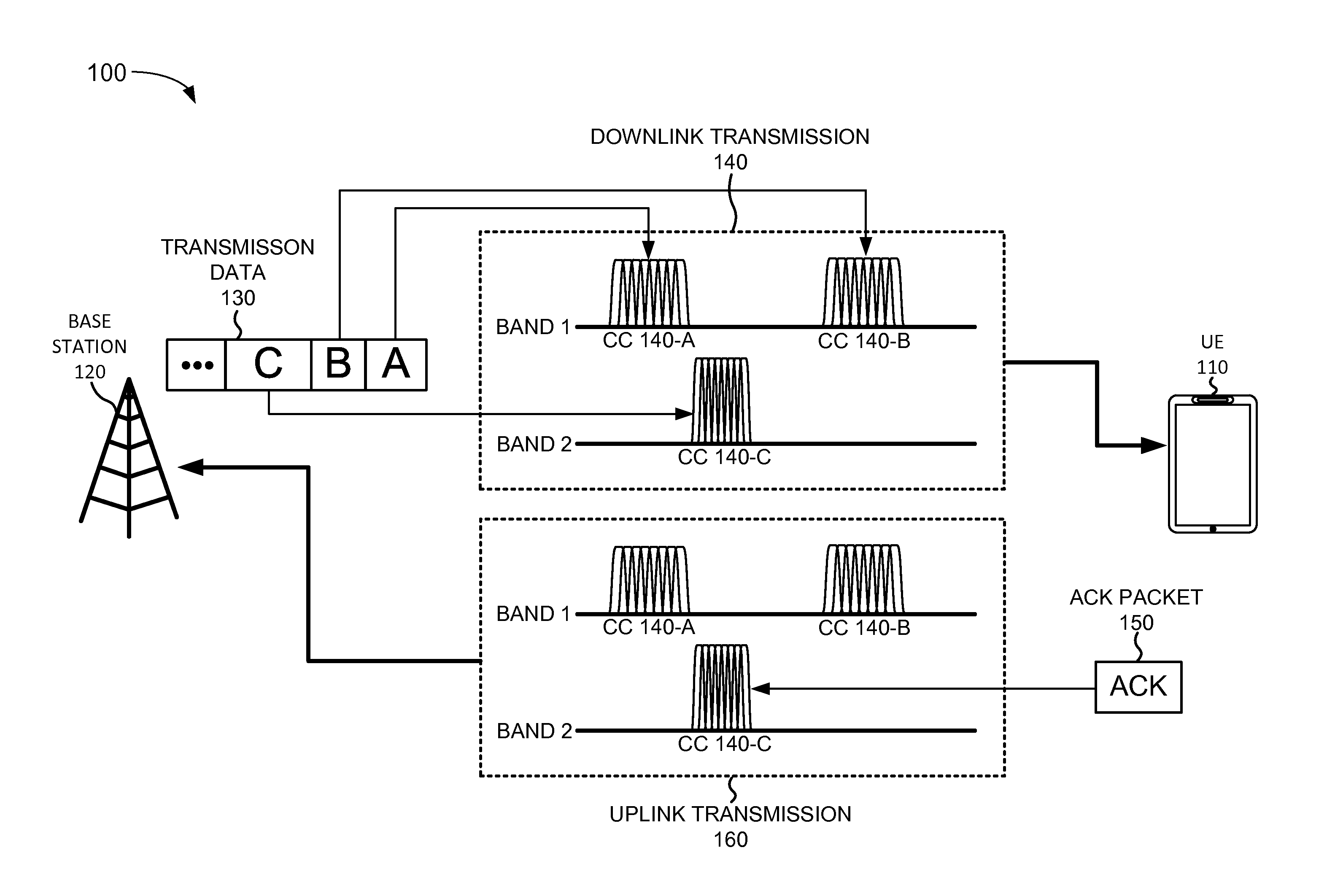
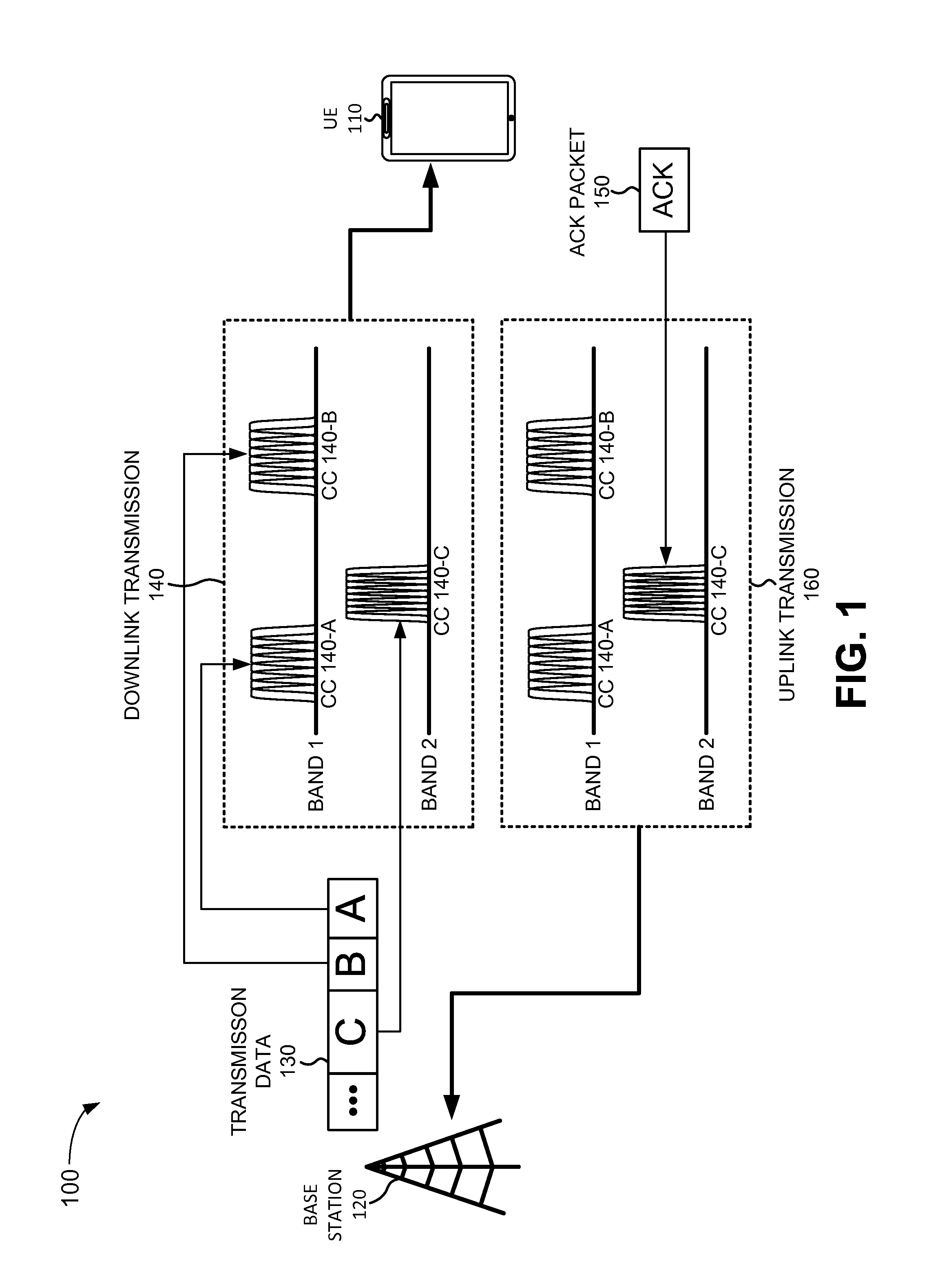
[0012]Implementations described herein relate to carrier aggregation management. Carrier aggregation is feature a wireless access network may use to increase bandwidth by using multiple downlink communication channels, referred to as component carriers. The downlink carrier aggregation may increase peak and average throughput on a downlink shared channel by aggregating two or more carriers' bandwidths and thus increasing effective downlink bandwidth. FIG. 1 is a diagram illustrating a carrier aggregation process 100 according to an implementation described herein. As shown in FIG. 1, downlink carrier aggregation process 100 may include user equipment (UE) 110 communicating with a base station 120. Base station 120 may receive transmission data 130 and may transmit transmission data 130 to UE 110.

[0013]Base station 120 (a...


PUM


Abstract

A computer device may include logic configured to configure carrier aggregation for a user equipment serviced by the base station device; activate a secondary component carrier for the user equipment; determine that a quality level for the secondary component carrier is lower than a quality threshold; and de-activate the secondary component carrier for the user equipment, in response determining that the quality level is lower than the quality threshold. The logic may be further configured to detect a problem associated with the primary component carrier for the user equipment; determine whether a better primary component carrier is available, in response to detecting the problem; switch to the better primary component carrier, when the better primary component carrier is available; and de-configure carrier aggregation for the user equipment, when the better primary component carrier for the user equipment is not available.

Description

BACKGROUND INFORMATION[0001]Mobile communication devices connect to a wireless access network via a base station. A base station may include a radio frequency (RF) transceiver configured to receive wireless signals from a mobile communication device and to transmit wireless signals to the mobile communication device. A base station may communicate with a large number of mobile communication devices. The large number of mobile communication devices may tax the resources of the base station.BRIEF DESCRIPTION OF THE DRAWINGS[0002]FIG. 1 is a diagram illustrating a downlink carrier aggregation process according to an implementation described herein;[0003]FIG. 2 is a diagram illustrating an environment according to an implementation described herein;[0004]FIG. 3 is a diagram illustrating exemplary components of the eNodeB of FIG. 1;[0005]FIG. 4 is a diagram illustrating exemplary functional components of the eNodeB of FIG. 1;[0006]FIG. 5 is a diagram illustrating exemplary components tha...

Claims


Application Information

Patent Timeline
IPC IPC(8): H04W72/08H04W72/04H04L5/00
CPCH04W72/0453H04L5/003H04W72/085H04L5/001H04L5/0098H04W72/542
Inventor PANCHAL, JIGNESH S.
Owner VERIZON PATENT & LICENSING INC
Why Eureka
Try Eureka