
Torsion Bar

a technology of rotating bars and rotating rods, applied in the field of rotating bars, can solve problems such as the risk of chipping

Inactive Publication Date: 2015-12-03
HILTI AG
View PDF6 Cites 3 Cited by
  • Summary
  • Abstract
  • Description
  • Claims
  • Application Information

AI Technical Summary

Benefits of technology

The present invention aims to provide a reliable torsion bar without involving a lot of work. The invention is based on the realization that the tapered torsion section of the shank of the torsion bar is deformed during normal operation. If a coating had been provided to protect against corrosion, it could have chipped since it cannot follow the movement of the substrate. To counter this, the invention provides a plastic encapsulation instead of a coating. The plastic encapsulation can be easily created with a relatively thick wall and exhibits ductility and minimal adhesion to the substrate. The plastic encapsulation can especially protect the sensitive tapered section against mechanical effects. Additionally, the invention allows for a central section of the shank to be protected while leaving the end sections free. The plastic encapsulation can be made of elastomer which can absorb deformation well. This results in excellent strength even if the plastic encapsulation adheres tightly to the shank.

Problems solved by technology

If a coating had been provided in this section as protection against corrosion, this could entail the risk of chipping since a coating—which is typically less ductile but adheres well to the substrate—cannot follow the movement of the substrate.

Method used


Image

  • Torsion Bar
  • Torsion Bar

Examples


Embodiment Construction

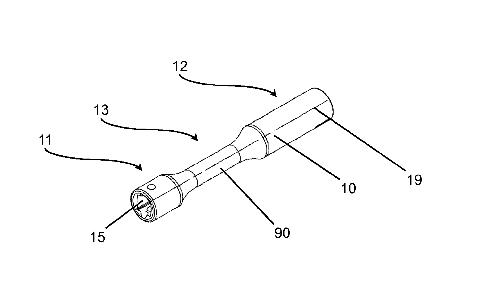
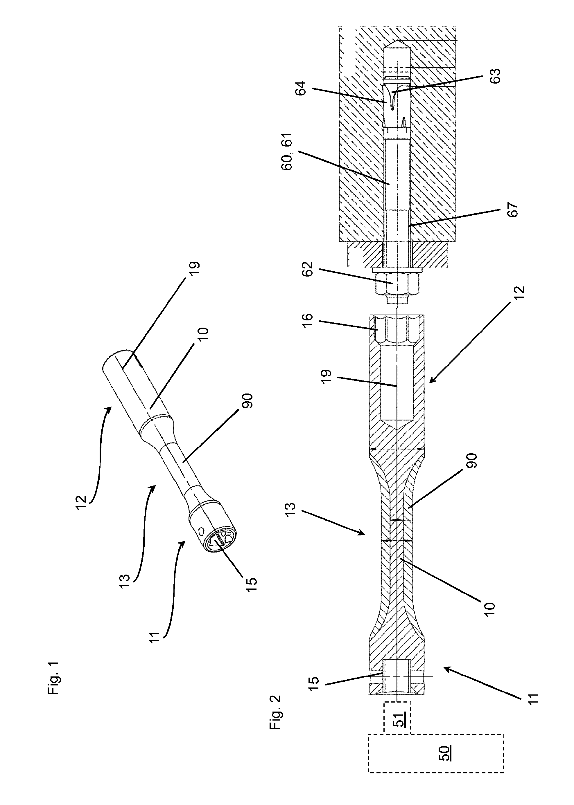
[0022]The figures show an embodiment of a torsion bar according to the invention. The torsion bar has a shank 10 with a first end section 11 and an opposite second end section 12 in a lengthwise direction, in other words, in the direction of the lengthwise axis 19 of the shank 10. On the first end section 11, the end face of the shank 10 has a first coupler 15 configured as a polygonal socket by means of which the shank 10 can be non-rotatably coupled to the driven spindle 51 of an impact driver 50, especially a tangential impact driver, which is only shown in FIG. 2, merely in a simple schematic form. On the second end section 12, there is on the end face of the shank 10 a second coupler 16 configured as a hexagonal socket by means of which the shank 10 can be non-rotatably coupled to a threaded element 62 that is only shown in FIG. 2.

[0023]In particular, the torsion bar can serve to install the expansion anchor 60 shown in FIG. 2, which has an anchor bolt 61 and an expansion sleev...


PUM


Abstract

A torsion bar for limiting torque, including a shank with a first end section and a second end section situated opposite from it in the lengthwise direction, also including a first coupler to non-rotatably join the shank to the driven spindle of an impact driver, whereby the first coupler is located on the first end section of the shank, and including a second coupler to non-rotatably join the shank to a threaded element, especially the nut of an expansion anchor, whereby the second coupler is arranged on the second end section of the shank, whereby the shank has at least one tapered torsion section in which the shank has a smaller cross section than in at least one of the end sections, characterized in that the shank has a plastic encapsulation, at least in the tapered torsion section.

Description

[0001]The invention relates to a torsion bar for limiting torque. The torsion bar has a shank with a first end section and a second end section situated opposite therefrom in the lengthwise direction, it also has a first coupler to non-rotatably join the shank to the driven spindle of an impact driver, whereby the first coupler is located on the first end section of the shank, it also has a second coupler to non-rotatably join the shank to a threaded element, especially the nut of an expansion anchor, whereby the second coupler is arranged on the second end section of the shank, whereby the shank has at least one tapered torsion section in which the shank has a smaller cross section than in at least one of the end sections.BACKGROUND[0002]A generic torsion bar is disclosed, for example, in British patent application GB 1521461 A. Such a torsion bar constitutes a torsion spring between the driven spindle of the impact driver and the screw element that is to be tightened, whereby said...

Claims


Application Information

Patent Timeline
Patent Type & Authority Applications(United States)
IPC IPC(8): B25B23/00B25B13/06B25B21/02B25G1/10
CPCB25B23/0021B25B21/02B25B13/06B25G1/105B25B31/00
Inventor WISSLING, MATTHIASECKSTEIN, ANDREASMEIER, ROBERTZITZMANN, RALF
Owner HILTI AG
Learn More