Magnetic recording medium

a magnetic recording medium and recording element technology, applied in the field can solve the problems of affecting the reproduction efficiency of mr head, and mr head being forced to be used with a low reproduction output, so as to reduce the grinding ability of magnetic recording mediums, enhance the uniform thickness of coating layers, and reduce the proportion of aggregates in the abrasiv

Inactive Publication Date: 2006-12-05
TDK CORPARATION
View PDF7 Cites 0 Cited by
  • Summary
  • Abstract
  • Description
  • Claims
  • Application Information

AI Technical Summary

Benefits of technology

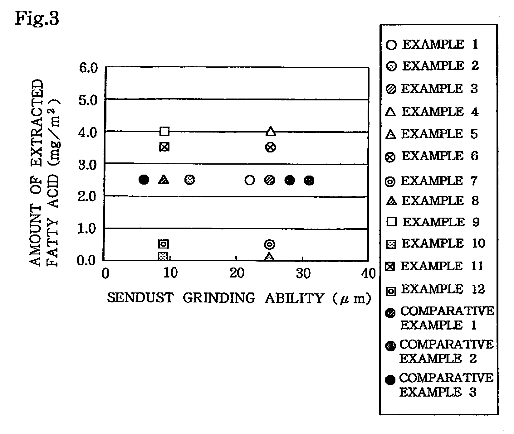
[0012]For manufacturing the magnetic recording medium having grinding ability as described above, the magnetic layer is formed by coating a magnetic paint comprising at least a ferromagnetic powder, a binder resin and an abrasive on the nonmagnetic supporting member as solid fractions. The step for producing the magnetic paint comprises adding the abrasive as a slurry to a kneaded product of the solid fractions except the abrasive, subjecting the resulting mixture to primary dispersion by diluting with a solvent, and then subjecting the mixture to secondary dispersion at a higher peripheral speed than that in the primary dispersion using a dispersion medium having a small diameter after the mixture is diluted with an additional solvent. As a result, grinding ability of the magnetic recording medium may be reduced in the range as described above by diminishing the proportion of aggregates in the abrasive. A so-called W / D (wet-on-dry) method is preferably used as the coating method in order to even the degree of protrusion from the surface of the abrasive on the coating layer of the magnetic layer by enhancing uniformity of the thickness of the coating layer on the magnetic layer.
[0013]Phthalic acid is preferably added in the magnetic layer in order to restrict the amount of the extracted fatty acid within the range as described above. Consequently, the amount of the fatty acids may be increased without changing the amount of addition of the fatty acids, and durability of the magnetic recording medium may be improved.
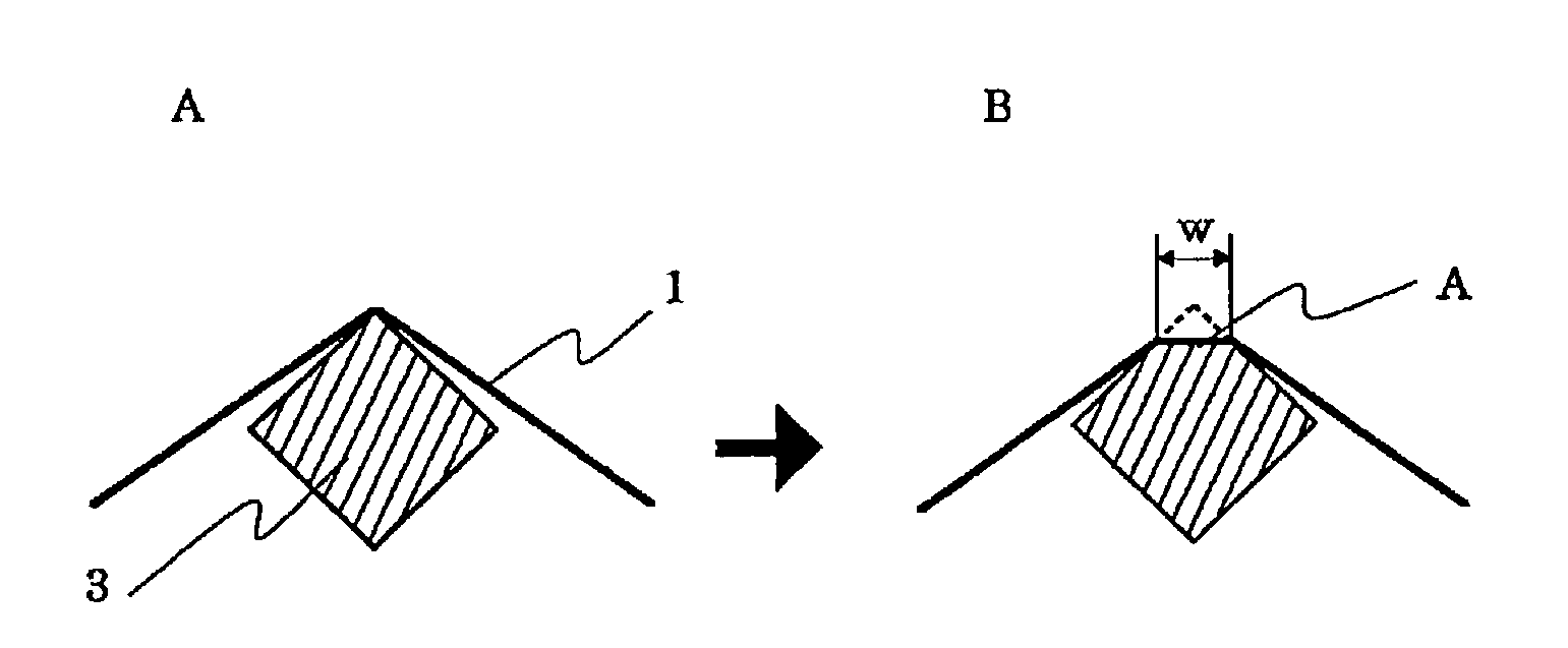
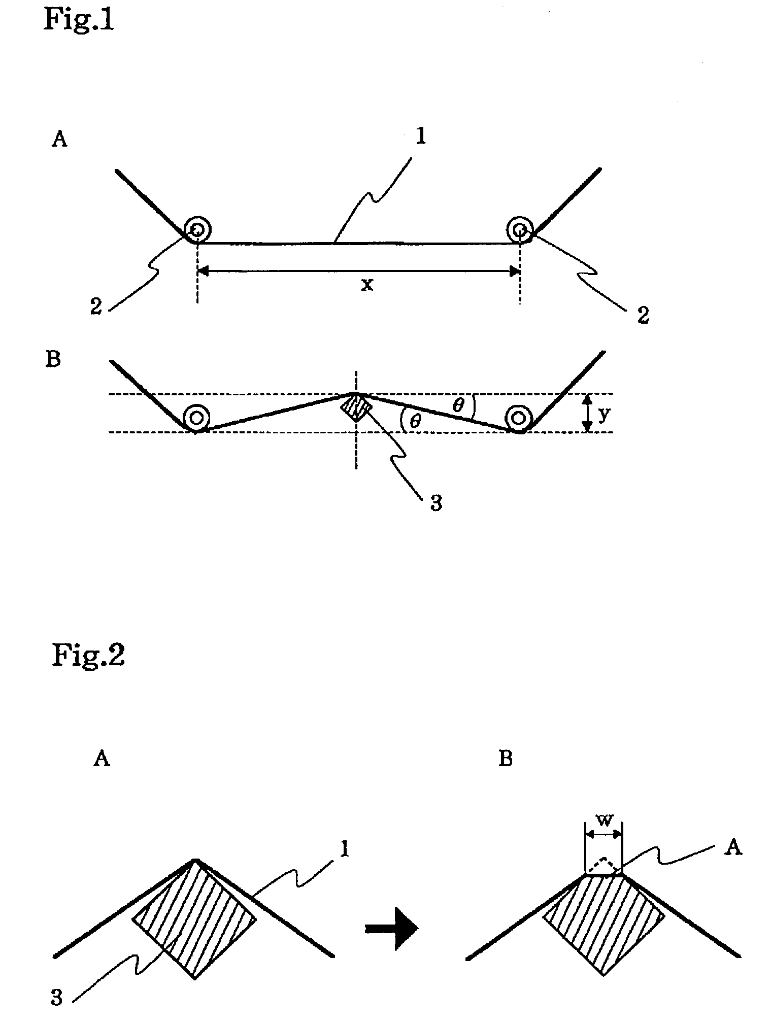
[0014]Japanese Unexamined Patent Application Publication No. 11-86265 discloses a technique for measuring grinding ability of the magnetic recording medium using the sendust bar, wherein the surface roughness of the magnetic tape is improved in order to improve the regeneration output while permitting the magnetic recording medium to have a surface hardness so that the amount of abrasion of sendust is within a specified range in order to avoid clogging of the magnetic tape. With respect to grinding ability, the patent publication described that the grinding effect is so insufficient that the magnetic tape is clogged when the amount of grinding is less than 15 μm, while the grinding effect is too large that the magnetic head is excessively worn when the amount of grinding exceeds 35 μm. However, since abrasion is investigated with respect to the inductive head, and nothing is described with respect to the MR head of the invention that is more susceptible to damages than the inductive head.

Problems solved by technology

However, since the MR element part of the MR head comprises a laminated thin layer, the MR head is liable to be damaged by direct sliding contact with a tape as well as by generation of smearing and electrostatic discharge (ESD) as compared with the inductive head.
When the head is damaged by these phenomenon and generation of flaws, the output of the MR element becomes unstable due to resistance changes of the MR head or the head does not substantially function, causing system faults in both cases.
However, since sensitivity of the MR element decreases by the countermeasures as described above, it is a problem that the MR head is forced to be used with a low reproduction output.

Method used


Image

  • Magnetic recording medium
  • Magnetic recording medium
  • Magnetic recording medium

Examples


example 1

[0046]

α-Fe2O3 (DB-65 made by Toda Kogyo Co.) 80 parts by weight(mean major axis length = 0.11 μm, mean minor axis length = 18 nm,BET specific surface area = 51 m2 / g)Carbon black (#850 made by Mitsubishi Chemical Co.) 20 parts by weight(mean particle diameter = 16 nm, BET specific surface area = 200 m2 / g,DBP oil absorption = 70 ml / 100 g)α-Al2O3 (HIT 60A made by Sumitomo Chemical Co.) 5 parts by weight(mean particle diameter = 0.18 μm, BET specific surface area = 12 m2 / g)Electron beam (EB) curable polyvinyl chloride copolymer 14 parts by weight(degree of polymerization = 300, polar group: —OSO3K = 1.5groups / molecule)EB curable polyurethane 6 parts by weight(Mn = 26,000, polar group: —OSO3Na = 1 group / molecule)Phthalic acid 2 parts by weightmethylethyl ketone (MEK)100 parts by weightToluene100 parts by weightCyclohexanone 50 parts by weight

[0047]After kneading the above composition, the kneaded product was dispersed using a horizontal pin-mill filled with 75% by volume of zirconia bead...

example 2

[0056]A magnetic tape sample was prepared by the same method as in Example 1, except that the mixture was dispersed at a peripheral speed of 15 m / s using a horizontal pin-mill filled with 75% by volume of zirconia beads with a diameter of 0.5 mm after adjusting the viscosity at 500 cps by adding the additives and solvents in the method for preparing the paint for the magnetic layer in Example 1.

example 3

[0057]A magnetic tape sample was prepared by the same method as in Example 1, except that the mixture was dispersed at a peripheral speed of 8 m / s using a horizontal pin-mill filled with 75% by volume of zirconia beads with a diameter of 0.5 mm after adjusting the viscosity at 500 cps by adding the additives and solvents in the method for preparing the paint for the magnetic layer in Example 1.


PUM

PropertyMeasurementUnit
displacementaaaaaaaaaa
diameteraaaaaaaaaa
speedaaaaaaaaaa

Abstract

The invention provides a high performance magnetic recording medium used in the magnetic recording system using the MR head for the regeneration head, wherein the magnetic recording medium does not damage the MR head by direct sliding contact while having durability and self-cleaning power enough for preventing abrasion of the magnetic recording medium itself.

Description

BACKGROUND OF THE INVENTION[0001]1. Field of the Invention[0002]The invention relates to a magnetic recording medium, particularly to a magnetic recording medium that can be favorably used in a magnetic recording system using an MR head as a reproduction head.[0003]2. Description of the Related Art[0004]Use of an inductive MR composite thin film head using an MR head as a reproductive head has been proposed in compliance with recent requirements of high density recording for magnetic recording media, The MR head is a reproduction head for sensing data by taking advantage of an MR (magnetoresistive) effect. Since this head has higher sensitivity than conventional heads and reproduction output thereof can be largely improved, a high density recording is possible in a magnetic recording system using the MR head as described above even in a magnetic recording medium having a small leak magnetic flux ascribed to a short recording wavelength.[0005]However, since the MR element part of the...

Claims


Application Information

Patent Timeline
Patent Type & Authority Patents(United States)
IPC IPC(8): G11B5/706B05D5/12G11B5/70G11B5/702
CPCG11B5/70
Inventor KITAMURA, KENICHIYAMADA, HIROYUKI
Owner TDK CORPARATION
Why Eureka
Try Eureka