Process for producing a fibrous bundle via a spinning nozzle

a spinning nozzle and fibrous bundle technology, applied in the field of spinning nozzles, can solve the problems of not being at a level that adequately responds to the needs of nanofibers, the limit of thinning the fiber diameter of about 2 m, and the cost increase, and achieves the effects of low cost, high efficiency and low adhesion

Active Publication Date: 2017-12-05
MITSUBISHI CHEM CORP
View PDF12 Cites 0 Cited by
  • Summary
  • Abstract
  • Description
  • Claims
  • Application Information

AI Technical Summary

Benefits of technology

[0051]According to the present invention, in a method using a super-porous spinning nozzle to directly spin with a wet spinning system, stable spinning is possible, and a fibrous bundle of uniform, continuous nanofibers can be produced at high efficiency, whereby ultrafine fibers having very little adhesion between single-fibers are provided.
[0052]In addition, when employing the fibers of the present invention, it is possible to provide paper excelling in strength despite having low paper density (weight per area).

Problems solved by technology

However, with conventional spinning methods based on melt spinning, wet spinning, etc., about 2 μm is the limit to thinning the fiber diameter, and it has not been at a level that adequately responds to the needs for nanofibers.
However, after spinning or after non-woven fiber manufacture, an abundant amount of the sea component must be removed from the solvent, which has become a cause of a cost increase due to the recovery or waste treatment of the removed sea component being necessary.
At the same time, these treatments have not been preferable in terms of the environment either.
However, the electrospinning method remains with a big problem in the productivity of industrial scale.
In other words, since the production volume of nanofibers is proportional to the number of spray nozzles, there is a limit in the technical issue of how much the number of spray nozzles is increased per unit area (or space).
In addition, since the polymer ejection volume from each spray nozzle is not fixed, there is a problem in variation in fiber diameter and variation in deposited amount in the non-woven fabric, problem of strength being weak due to drawing not being possible, problem in not being usable by making into short fibers, etc.
In addition, the occurrence of corona discharge can be given as a problematic issue in production derived from using spray nozzles.
When a corona discharge occurs, the applying of high voltage to the spray nozzle tip becomes difficult, and the accumulation of sufficient electric charge to the polymer solution inside the spray nozzle is not carried out, and thus it becomes difficult to form nanofibers.
Although various methods for suppressing this corona discharge have been considered, the solution has been difficult.
The problem in the productivity from employing such an electrospinning method is derived from using spray nozzles; therefore, considerations of electrospinning methods that do not use spray nozzles are also being carried out.
However, there remains the problem of the spinning state being very unstable with this method.
However, there is a limit in the area of the rotating roll portion to be spun, and thus there has been a problem in being necessary to increase the rotating roll diameter or increase the number of rotating rolls in order to further raise productivity, which leads to a size increase in the production facilities.
However, with this method, upon causing foam to form at the surface of the polymer solution and causing the polymer fiber jet to fly from the top of the foam, there is a problem in that the fine spray from the breaking off of the foam will fly and adhere to the nanofiber surface.

Method used


Image

  • Process for producing a fibrous bundle via a spinning nozzle
  • Process for producing a fibrous bundle via a spinning nozzle
  • Process for producing a fibrous bundle via a spinning nozzle

Examples


example 1

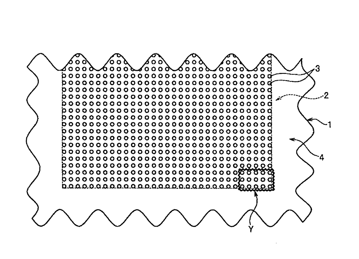
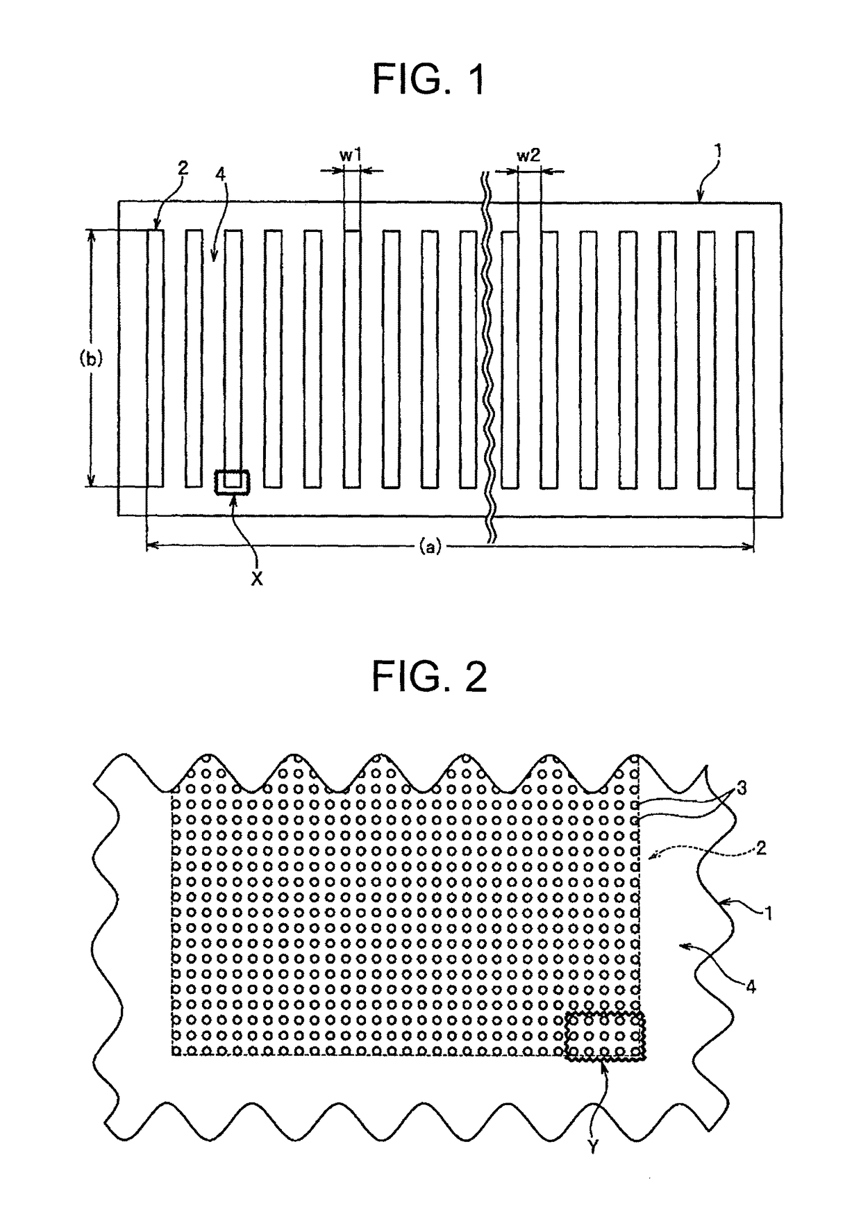
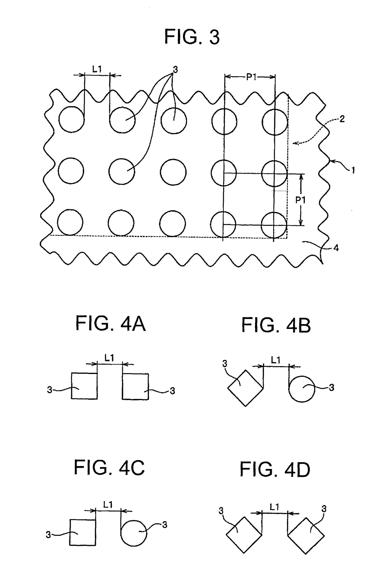
[0158]A spinning nozzle with a hole density of 1,111 holes / mm2, ejection hole area of 176.6 μm2, ejection hole inter-outer edge distance of 0.015 mm, perforated part width of 1 mm, inter-perforated part distance of 2 mm, number of perforated parts of 30, and total number of holes of 1.17×10⁶ holes was created using nickel as the material by Semtech Engineering Co., Ltd. by the electroforming method. The ejection hole arrangements are as shown in FIGS. 1 to 3.

[0159]A spinning dope was prepared with 16% by mass polymer concentration by dissolving a polymer of 0.200 specific viscosity consisting of 91% by mass of acrylonitrile units and 9% by mass of vinyl acetate units (dissolving 0.5 g of polymer is 100 ml of dimethylformamide, measured at 30° C.; similarly in the following) in dimethylformamide (hereinafter abbreviated as DMAc), and then filtering with a sintered metal filter of 5 μm filtration accuracy. The viscosity thereof was 70 poise at 50° C.

[0160]Next, the spinning dope was e...

examples 2 to 7

[0165]Fibrous bundles were obtained by performing spinning in the same way as Example 1, except for using the nozzles described in Table 1.

[0166]The spinning results thereof are shown in Table 1.

[0167]Examples 2 to 5 and 7 were able to be spun without thread breakage or entwining. Although a slight amount of adhered fibers formed, it was not to an extent that would become a problem.

[0168]In Example 6, the amount of adhered fibers became great compared to Example 1; however, it was in a range still usable in terms of quality. As the cause for the adhesion increasing, it is considered that the perforated part width became larger at 3 mm, and thus the flow of coagulation liquid to the central part of the perforated part worsened.

reference example 1

[0169]A fibrous bundle was obtained by performing spinning in the same way as Example 1, except for using the nozzle described in Table 1.

[0170]The spinning results thereof are shown in Table 1.

[0171]With Reference Example 1, although thread breakage of single fibers in the coagulation bath occurred, the quality of the fiber bundle was within a sufficiently usable range. The cause of this thread breakage is considered to be because, although the ejection hole area of the spinning nozzle was increased to facilitate ejection, in order to make the fineness match with the other examples, the draft ratio in the coagulation bath was raised.

[0172]Upon observing the obtained fiber bundle with a scanning electron microscope, fibers of nano-order level at 800 to 1,200 nm were observed.


PUM

PropertyMeasurementUnit
areaaaaaaaaaaa
areaaaaaaaaaaa
inter-outer edge distanceaaaaaaaaaa

Abstract

A spinning nozzle which has a perforated part in which ejection holes have been arranged in a density as high as 600-1,200 holes / mm2. This process for producing a fibrous bundle comprises ejecting a spinning dope having a viscosity as measured at 50° C. of 30-200 P from the ejection holes of the spinning nozzle to produce a fibrous bundle. This fibrous bundle has a single-fiber fineness of 0.005-0.01 dtex. By the wet-process direct spinning, a mass of nanofibers which are stably uniform and continuous can be produced at a high efficiency.

Description

TECHNICAL FIELD[0001]The present invention relates to a spinning nozzle made by suitably arranging ejection holes so that a coagulation liquid uniformly infiltrates all of the ejection holes in a super-porous nozzle arranging small diameter ejection holes in high density for the production of ultrafine fibers; a process for producing uniform micro fibers having a single-fiber fineness of nano (sub-micron) order using this spinning nozzle; and a fibrous bundle and paper obtained from this production process.BACKGROUND ART[0002]Synthetic fibers are mainly used in clothing applications, and many considerations have come to be actively made for polymer modification, modifying cross sections, imparting functionality, increasing fineness, and the like in order to improve the performance and texture thereof. In particular, the increased fineness of single fibers has led to the progression of suede-tone artificial leather from the development of micro fibers, and this basic technology there...

Claims


Application Information

Patent Timeline
Patent Type & Authority Patents(United States)
IPC IPC(8): D01D5/04D01D4/02D01D5/06D01D10/06D01F6/18D21H13/18
CPCD01D5/06D21H13/18D01F6/18D01D4/02D04H1/43
Inventor KOTERA, YOSHINOBUONOHARA, YUKIONAKANISHI, SHIMA
Owner MITSUBISHI CHEM CORP
Why Eureka
Try Eureka