Fiber strap packing machine

Active Publication Date: 2015-12-03
CHEN HSIU MAN YU
View PDF7 Cites 2 Cited by
  • Summary
  • Abstract
  • Description
  • Claims
  • Application Information

AI Technical Summary

Benefits of technology

[0008]The power unit of the fiber strap packing machine of the present invention uses high pressure gas as the power source for the main body to fasten the fiber strap automatically to encircle an article to be baled. After that, the fiber strap is pulled to the strap rolling unit and the power unit is started. The fiber strap is rolled backward by the strap rolling unit to be tightened gradually. Whe

Problems solved by technology

The operation is time-consuming.
The user will feel tired easily after a period of time.
This lowers the packing efficiency.
When

Method used


Image

  • Fiber strap packing machine
  • Fiber strap packing machine
  • Fiber strap packing machine

Examples


Example

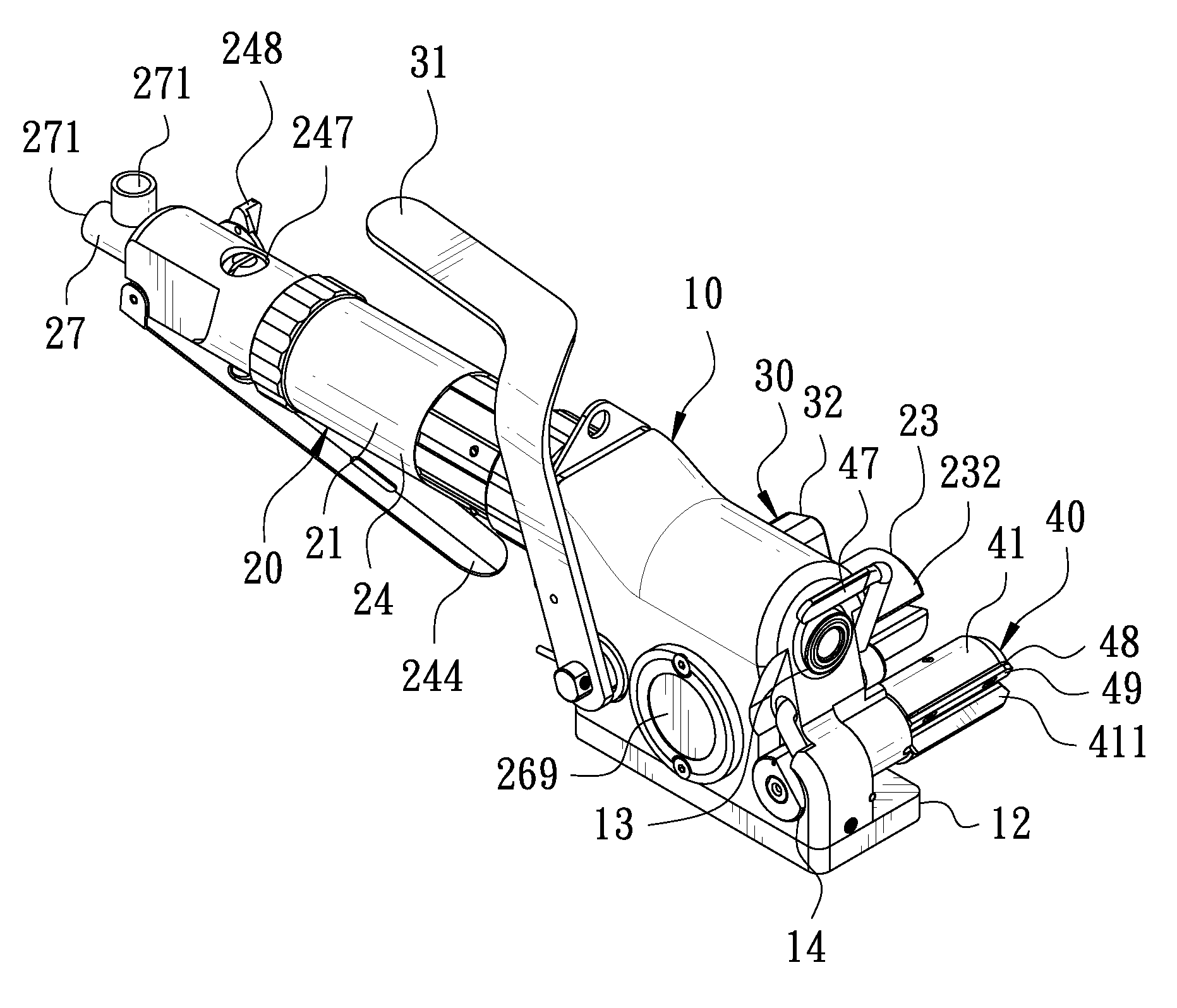
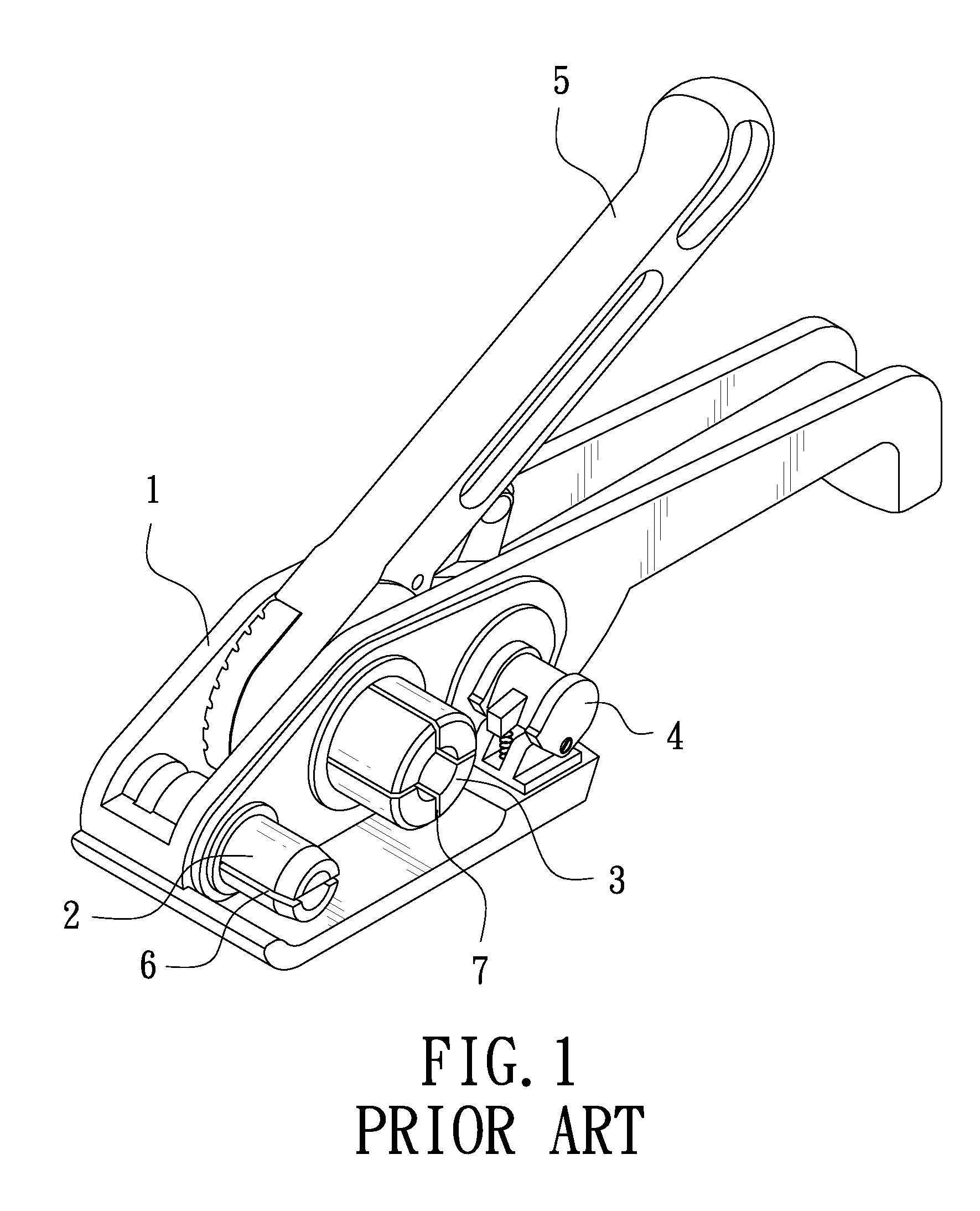
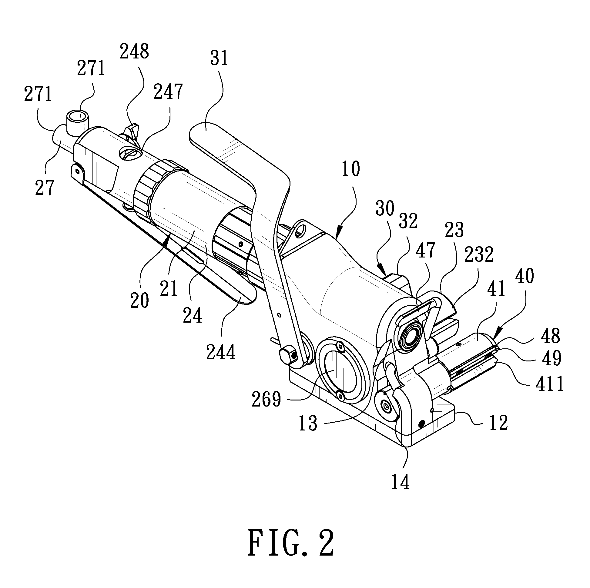
[0022]FIG. 2 is a perspective view according to a first embodiment of the present invention. FIG. 3 is a partial exploded view according to the first embodiment of the present invention. The present invention discloses a fiber strap packing machine. The fiber strap packing machine comprises a main body 10 and a fastening device 20.

[0023]The main body 10 has a drive space 11 therein. The bottom of the main body 10 is provided with a base 12. The outer side of the main body 10 has a first connecting hole 13, a second connecting hole 14, a third connecting hole 15, and a fourth connecting hole 16. Referring to FIG. 6, the first connecting hole 13 is located above the second connecting hole 14, the third connecting hole 15, and the fourth connecting hole 16. The first connecting hole 13 and the second connecting hole 14 communicate with the drive space 11.

[0024]The fastening device 20 is disposed at one side of the main body 10 relative to the connecting hole 13. The fastening device 20...

Example

[0035]FIG. 11 is a partial exploded view according to a second embodiment of the present invention. FIG. 12 is a partial perspective view according to the second embodiment of the present invention. The second embodiment is substantially similar to the first embodiment with the exceptions described hereinafter. The tension adjustment unit 22 is provided with an output shaft. The output shaft is connected with the strap pressing device 30. In the second embodiment of the present invention, the output shaft is the spindle 232. The tension adjustment unit 22 is disposed between the worm gear 265 and the spindle 232. The adjustment member 222 of the tension adjustment unit 22 comprises a first adjustment member 28 and a second adjustment member 29. The first adjustment member 28 and the second adjustment member 29 mate with each other. The first adjustment member 28 is mounted to the worm gear 265. The elastic member 223 is disposed between the second adjustment member 29 and the fasten...


PUM

PropertyMeasurementUnit
Sizeaaaaaaaaaa
Tensionaaaaaaaaaa

Abstract

A fiber strap packing machine includes a main body. One side of the main body is provided with a fastening device, a cutting device, and a strap pressing device. The fastening device includes a power unit, a tension adjustment unit, and a strap rolling unit. The power unit is connected with the tension adjustment unit and the strap rolling unit. When the strap rolling unit is tightened by a fiber strap, the power of the power unit will be transmitted to the tension adjustment unit through the fastening device. The tension adjustment unit stops the power to be transmitted to the strap rolling unit so as to automatically adjust the tightness of the fiber strap and prevent the tightening device from being damaged by the external force and the power.

Description

BACKGROUND OF THE INVENTION[0001]1. Field of the Invention[0002]The present invention relates to a packing machine, and more particularly to a pneumatic packing machine used for fiber straps.[0003]2. Description of the Prior Art[0004]FIG. 1 is a perspective view of a conventional packing machine. The packing machine comprises a main body 1. One side of the main body 1 is provided with a cutting device 2, a tightening device 3, and a pressing device 4 which are arranged from front to back in sequence. A press handle 5 is mounted on top of the main body 1. After an article is baled by a fiber strap, one end of the fiber strap is inserted into the bottom of the pressing device 4 and then pressed and secured thereat. The other end of the fiber strap is inserted through a strap inlet 6 of the cutting device 2 and into a groove 7 of the fastening device 3. Afterward, the press handle 5 is turned properly for the fiber strap to be rolled backward gradually by the tightening device. After t...

Claims


Application Information

Patent Timeline
IPC IPC(8): B65B13/18B65B13/24B65B13/22B65B13/16
CPCB65B13/188B65B13/22B65B13/24B65B13/16B65B13/025B65B13/34
Inventor YU CHEN, HSIU-MAN
Owner CHEN HSIU MAN YU
Why Eureka
Try Eureka