Multiple-plate clutch

Inactive Publication Date: 2015-12-03
VOLVO LASTVAGNAR AB
View PDF5 Cites 5 Cited by
  • Summary
  • Abstract
  • Description
  • Claims
  • Application Information

AI Technical Summary

Benefits of technology

[0028]In order to give the force enhancement means an even greater effect it can further comprise a lever arm with a flyweight. The lever arm is provided with a first flyweight and acts upon said separating means. The lever arm is provided upon a pivot pin fixed to the plate carrier corresponding to said first plate set, whereby said first flyweight is arranged upon said lever arm at a distance from said pivot pin and said separating means, such that centrifugal force acting upon said flyweight generates an enhancement force acting upon said separating means, such that the enhancement force acts

Problems solved by technology

In general, they can neither be engaged nor disengaged while transferring any significant amount of power.
Thus, at gear shifts several vehicle transmission designs with tooth clutches have an interruption of the power transfer between prime mover (engine) and driven wheels.
This is a rather slow process, which limits the slipping capability of dry plate clutches.
Moreover, the surfaces in contact are worn, implying a limited durability.
However, for more demanding applications, dry plate clutches are not suitable.
This has a considerable impact on the friction in the contacting surfaces.
Secondly, one actuation force can act on all surfaces.
However, the plurality of plates in a wet plate clutch will cause power losses in disengaged state when the rotating units have different rotational speeds.
Oil between the surface

Method used


Image

  • Multiple-plate clutch
  • Multiple-plate clutch
  • Multiple-plate clutch

Examples


Example

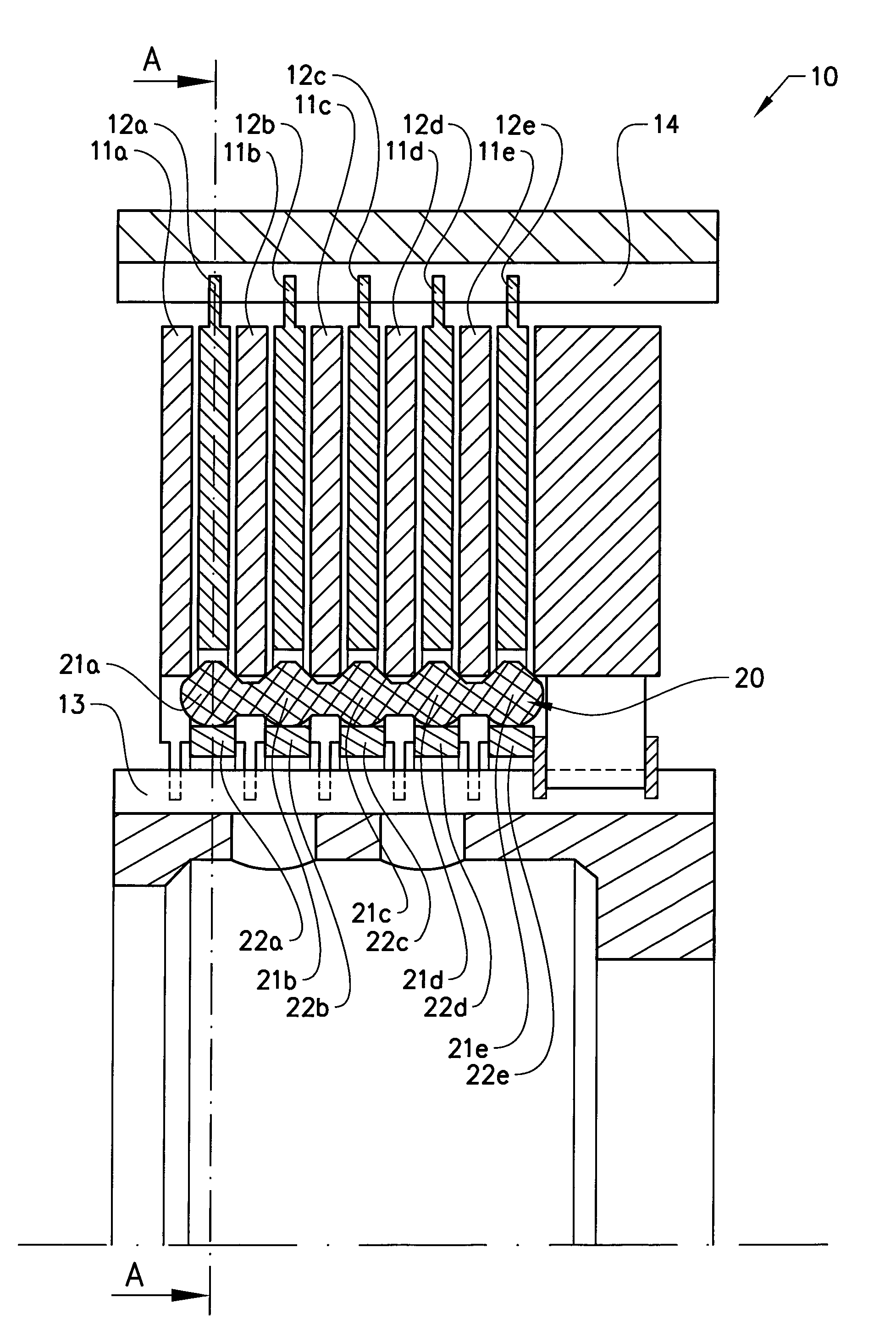
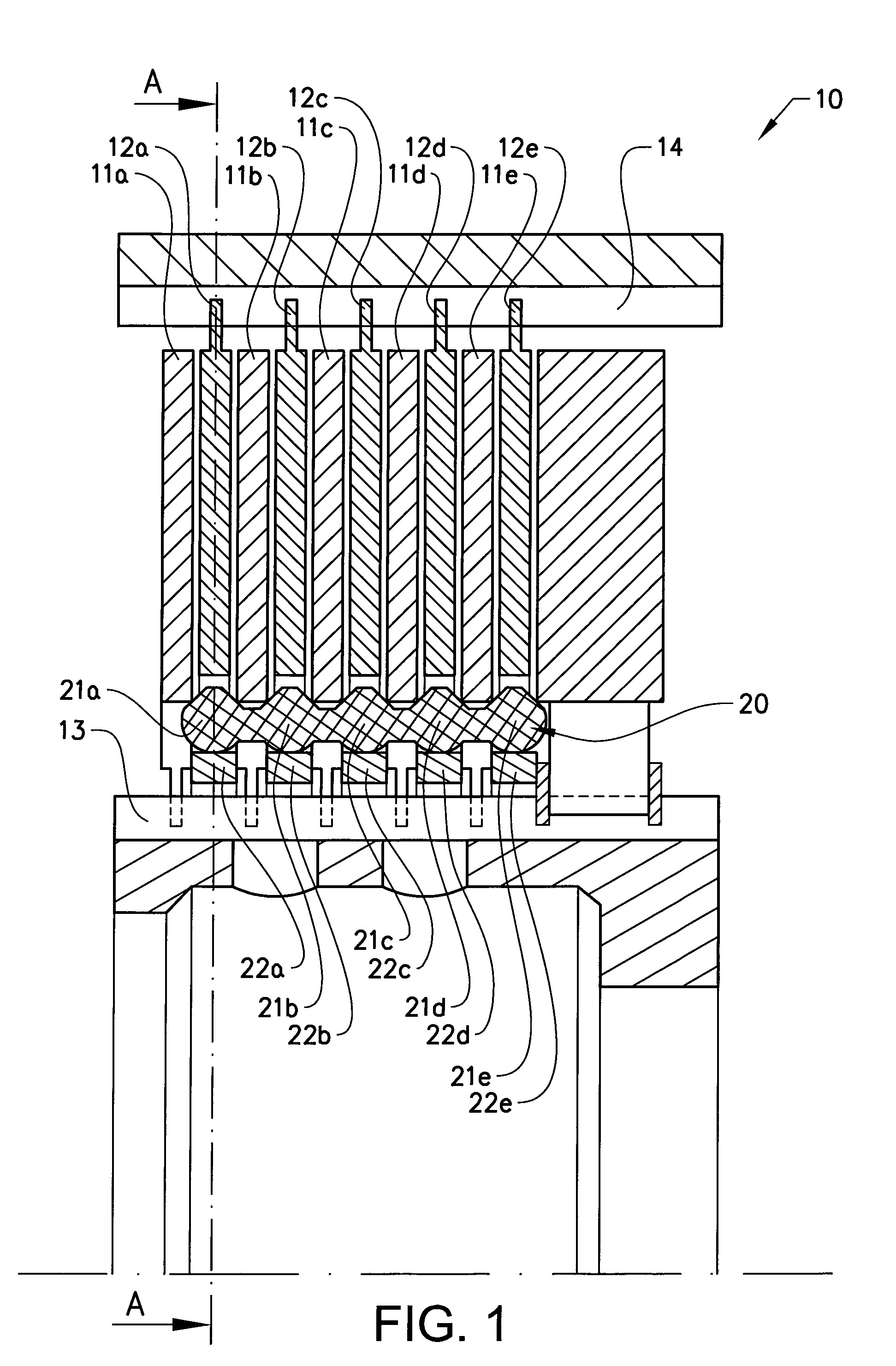
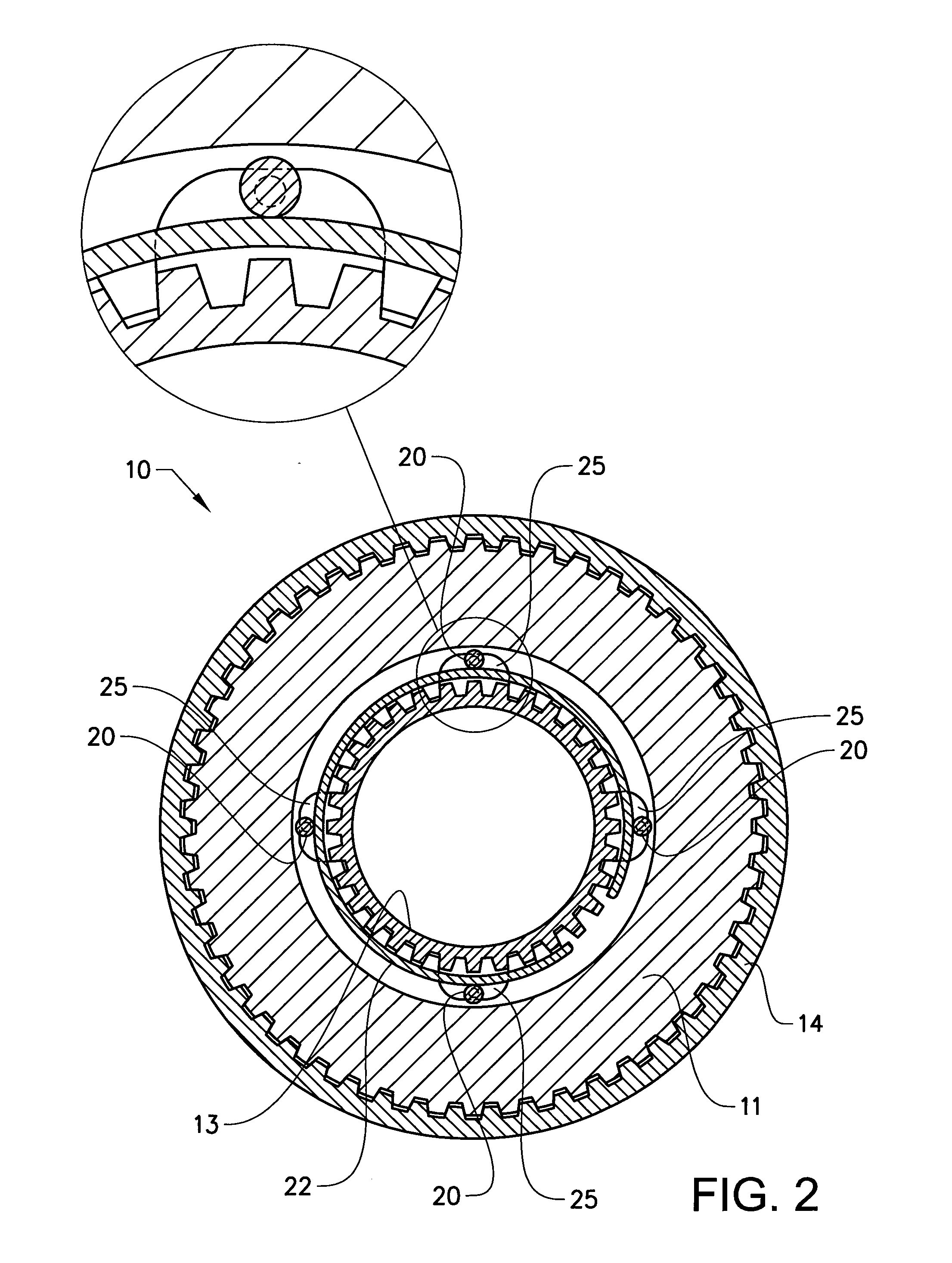
[0041]FIG. 1 discloses a part of a multiple-plate clutch 10, having an inner clutch set 11 provided with a plurality of inner clutch plates 11a, b, c, d, e and an outer clutch set 12 provided with a plurality of outer clutch plates 12a, b, c, d, e. The multiple-plate clutch is provided within a not shown clutch housing. The inner and outer clutch sets 11, 12 are arranged upon an inner and outer plate carrier 13, 14 upon which the clutch plates 11a-e, 12a-e are arranged such that the clutch plates 11a-e, 12a-e are rotationally fixed thereupon and displaceable in axial direction. The general features and functions of a multiple-plate clutch 10 are known and will therefore not be further explained.

[0042]The multiple-plate clutch 10 disclosed in FIG. 1 is provided with a separating means 20, which is provided as an axially extending bar provided with protrusions 21a-e intended to protrude in between the individual inner clutch plates 11a-e. The separating means 20 can also be provided s...


PUM


Abstract

A multiple-plate clutch includes a first set of plates and a second set of plates, wherein one of the first and second set of plates is a set of internal plates and the other is a set of external plates, the plates of each set being mounted on a respective plate carrier so that they are axially displaceable but not rotatable relative to the respective plate carrier, wherein the first set is provided with a separating arrangement which extends axially over all of the plates of at least the first set of plates and is arranged in between each pair of adjacent plates of at least the first set of plates and is provided such that the separating arrangement is adapted to wedge in between the respective adjacent plates. The separating arrangement is provided with a force enhancement arrangement which adds a radial force to the separating arrangement, wherein the force enhancement arrangement is at least a resilient member acting upon the separating arrangement to enhance the wedging in between the respective adjacent plates.

Description

BACKGROUND AND SUMMARY[0001]The present invention relates to the field of friction clutches and especially multiple-plate friction clutches and separating means therefore.[0002]Stepped transmissions for vehicles are robust, compact and cost-effective products. A stepped transmission can be designed using gearwheels that rotate about fix axes, with planetary gear trains, or combinations thereof. A typical example of a fix-axes lay-out is shown in DE19821164A1. A modern transmission design using planetary gear trains can be seen in[0003]DE102005010210A1. Combinations of fix axes and planetary gear trains are found in, e.g., U.S. Pat. No. 5,351,569 and EP1211436A2. Basically, different gears are obtained by rotationally connecting different parts. This is done by shift clutches that can engage two rotating units. There are two main types of shift clutch; positively engaging tooth clutches and friction clutches. Tooth clutches have an “on-off” behaviour; they are either engaged or disen...

Claims


Application Information

Patent Timeline
IPC IPC(8): F16D13/69F16D13/64
CPCF16D13/648F16D13/69F16D13/52
Inventor ERHARD, HANSHEDMAN, ANDERS
Owner VOLVO LASTVAGNAR AB
Why Eureka
Try Eureka