Gearbox for a motor vehicle

Active Publication Date: 2015-12-03
GETRAG GETRIEBE & ZAHNRADFABRIK HERMANN HAGENMEYER GMBH & CO KG
View PDF75 Cites 7 Cited by
  • Summary
  • Abstract
  • Description
  • Claims
  • Application Information

AI Technical Summary

Benefits of technology

[0111]If the valve which connects the fluid reservoir and the fluid sump is supplied with extraneous energy, the valve can be placed in an opened state, with t

Problems solved by technology

Gear wheels which are contained in gearboxes known from the prior art usually dip at least partially into oil and as a result cause splashing losses as a function of the level of the oil.
Instead of the valve described above, which is normally prestressed in the “normally closed” manner, the valve can also be embodied as a “

Method used


Image

  • Gearbox for a motor vehicle
  • Gearbox for a motor vehicle
  • Gearbox for a motor vehicle

Examples


Example

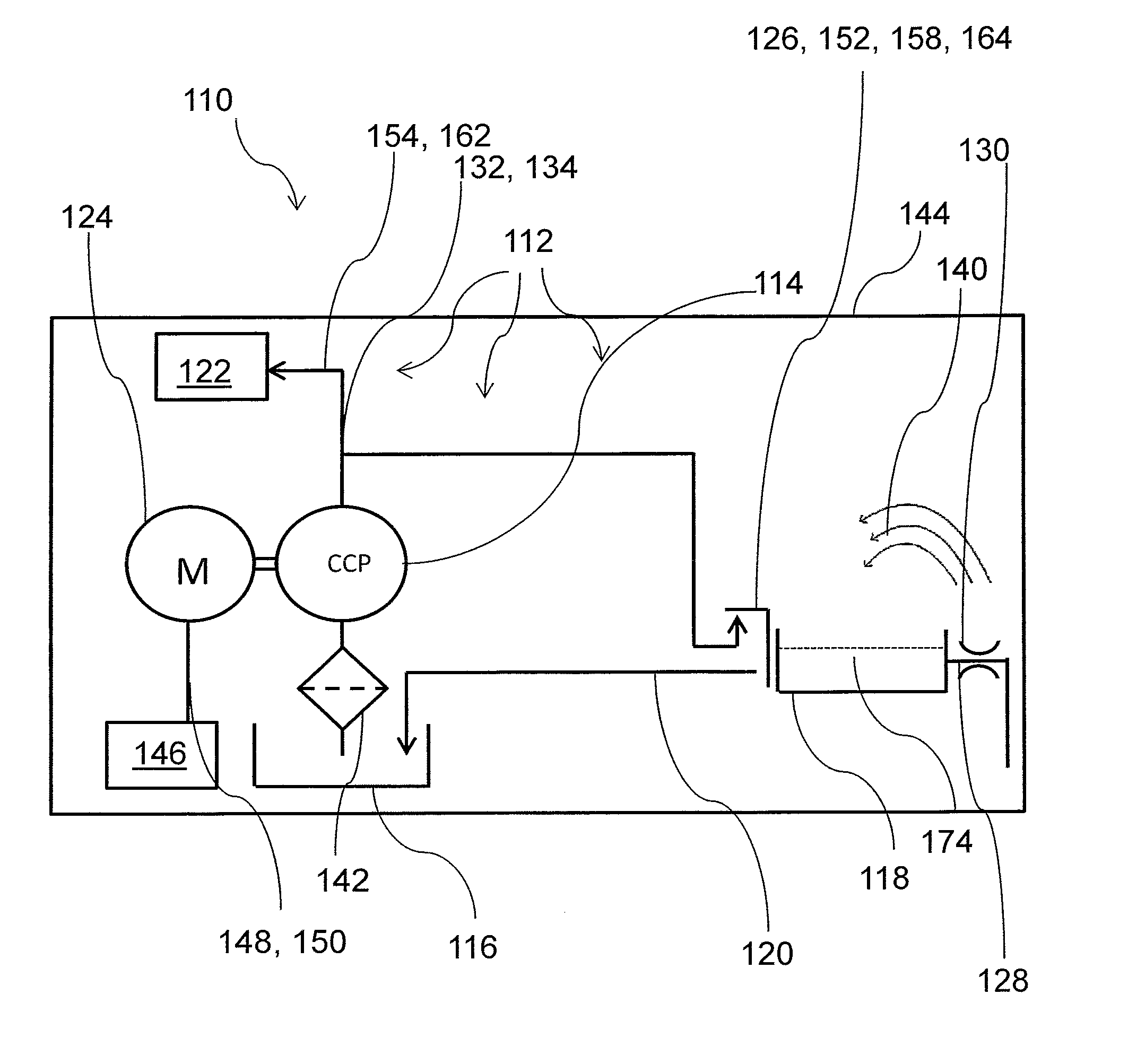
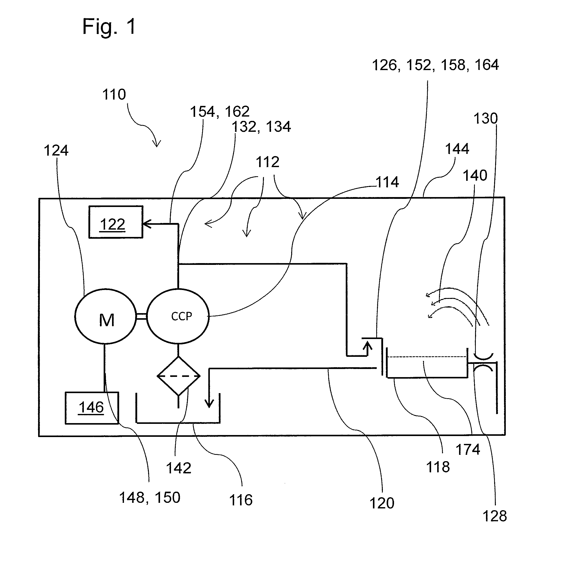
[0131]FIG. 1 illustrates a first exemplary embodiment of a gearbox 110 according to the invention.

[0132]The gearbox 110 comprises at least one fluid supply system 112. The fluid supply system 112 comprises at least one pump 114.

[0133]The fluid supply system 112 comprises at least one fluid sump 116. The fluid supply system 112 comprises at least one fluid reservoir 118. The fluid reservoir 118 comprises at least a first fluid outflow 120 leading into the fluid sump 116. The first fluid outflow 120 can be controlled as a function of a state variable.

[0134]The fluid sump 116 can be, for example, a gearbox oil sump.

[0135]The fluid reservoir 118 can in particular be configured to store at least a portion of a volume of fluid 174 in the fluid reservoir 118. The fluid sump 116 can be configured to store and / or contain at least a further portion of the volume of fluid 174.

[0136]The fluid reservoir 118 can be, for example, at least one container.

[0137]The gearbox 110 can comprise at least o...


PUM


Abstract

A gearbox for a motor vehicle. The gearbox comprises at least one fluid supply system. The fluid supply system comprises at least one pump. The fluid supply system comprises at least one fluid sump. The fluid supply system comprises at least one fluid reservoir. The fluid reservoir comprises at least a first fluid outflow leading into the fluid sump. The first fluid outflow can be controlled as a function of a state variable.

Description

CROSS-REFERENCE TO RELATED APPLICATIONS[0001]This application claims the priority of German patent application DE 10 2014 107 659, filed on May 30, 2014.BACKGROUND OF THE INVENTION[0002]The present invention relates to a gearbox for a motor vehicle and to a method for operating the gearbox.[0003]Gearboxes for motor vehicles are known which comprise elements which can be lubricated and / or cooled and / or hydraulically actuated by oil. A gearbox usually has an oil sump for this purpose. Gearboxes known from the prior art usually have a high oil level in the gearbox in order to be able to ensure a reliable oil supply in all driving states.[0004]DE 1 801 917 discloses a gearbox which operates with oil sump lubrication, in particular a differential gear for the axial drive of motor vehicles. A space which is divided off by a dividing wall and is open in its upper region is arranged within the gearbox housing in such a way that at least a portion of the oil which is thrown up during operati...

Claims


Application Information

Patent Timeline
IPC IPC(8): F16H57/04
CPCF16H57/0473F16H57/0436F16H57/0446F16H57/045F16H57/0409F16H57/0447F16H57/0457
Inventor SCHWEIHER, MARKEGGERT, ULRICHHEGERATH, ANDREAS
Owner GETRAG GETRIEBE & ZAHNRADFABRIK HERMANN HAGENMEYER GMBH & CO KG
Why Eureka
Try Eureka