
Three-dimensional molding device and three-dimensional molding method

a three-dimensional molding and molding device technology, applied in the direction of additive manufacturing processes, manufacturing tools, applying layer means, etc., can solve the problems of limited discharge of granular materials to other ranges, large workload, time-consuming, etc., and achieve the effect of reducing workload

Inactive Publication Date: 2019-09-17
TOYOTA JIDOSHA KK
View PDF10 Cites 2 Cited by
  • Summary
  • Abstract
  • Description
  • Claims
  • Application Information

AI Technical Summary

Benefits of technology

The patent text describes a three-dimensional molding device that allows for the efficient use of granular material in the molding process, reducing waste and production time. The device uses a layer-by-layer approach to create the desired shape, resulting in a more precise and efficient molded object.

Problems solved by technology

This causes a problem that a workload is large and it is time consuming.
This means that, it is possible to limit discharge of the granular material into a range that does not prevent forming of the solidifying region of the granular material.
In other words, the granular material is discharged and laminated in a range that covers a region corresponding to a transverse-sectional shape required for lamination and molding of the molded object, and the discharge of the granular material to other range is limited.

Method used


Image

  • Three-dimensional molding device and three-dimensional molding method
  • Three-dimensional molding device and three-dimensional molding method
  • Three-dimensional molding device and three-dimensional molding method

Examples


first embodiment

[0030]Herein below, embodiments of the disclosure are explained in detail with reference to the drawings. FIG. 1 to FIG. 6 are views of a three-dimensional molding device of the disclosure.

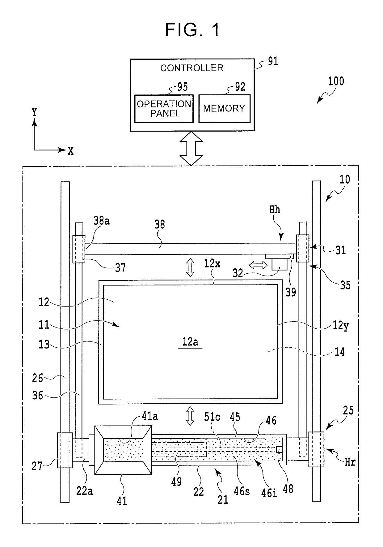
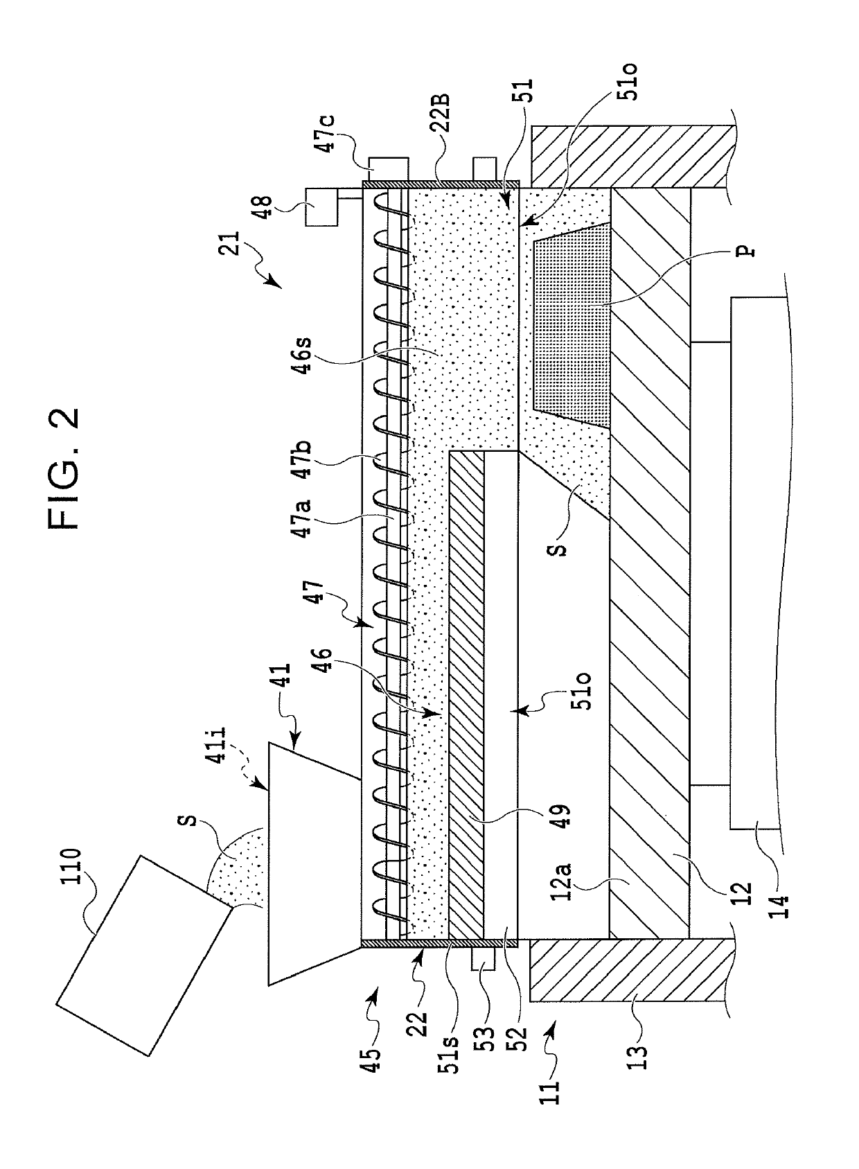
[0031]In FIG. 1 and FIG. 2, a three-dimensional molding device 100 of the embodiment is constructed by including an elevating table device 11, a powder and grain material lamination device 21, a binder injection device 31, and a controller 91, and the controller 91 performs integrated control of each of the devices 11, 21, 31 of a drive system 10.

[0032]The three-dimensional molding device 100 repeats a molding process operation. In the molding process operation, the powder and grain material lamination device 21 discharges and laminates a powder and grain material, for example, molding sand S, onto an upper surface 12a of a molding table 12 of the elevating table device 11, thereby forming a discharged layer L, and, the binder injection device 31 injects a liquid binder to a partial region of the ...

second embodiment

[0083]Next, FIG. 7 and FIG. 8 are views explaining the three-dimensional molding device according to the disclosure, and FIG. 9 is a view explaining an embodiment according to a three-dimensional molding method of the disclosure in which the three-dimensional molding device is used. Here, since this embodiment is structured almost similarly to the foregoing embodiment, the same drawings are used, and the same reference numerals are used for similar constituents to explain features.

[0084]In FIG. 1 and FIG. 4, a controller 91 of a three-dimensional molding device 100 according to the embodiment creates transverse-sectional shape data of a wall-shaped object solidified region Hw for each layer based on received stereoscopic data of a molded object P, and stores (sets) the data inside a memory 92. In the wall-shaped object solidified region Hw, a wall-shaped object W is molded outside a molded object solidified region Hp of the molded object P. The wall-shaped object W is laminated toge...


PUM

PropertyMeasurementUnit
elongated shapeaaaaaaaaaa
distanceaaaaaaaaaa
lengthsaaaaaaaaaa

Abstract

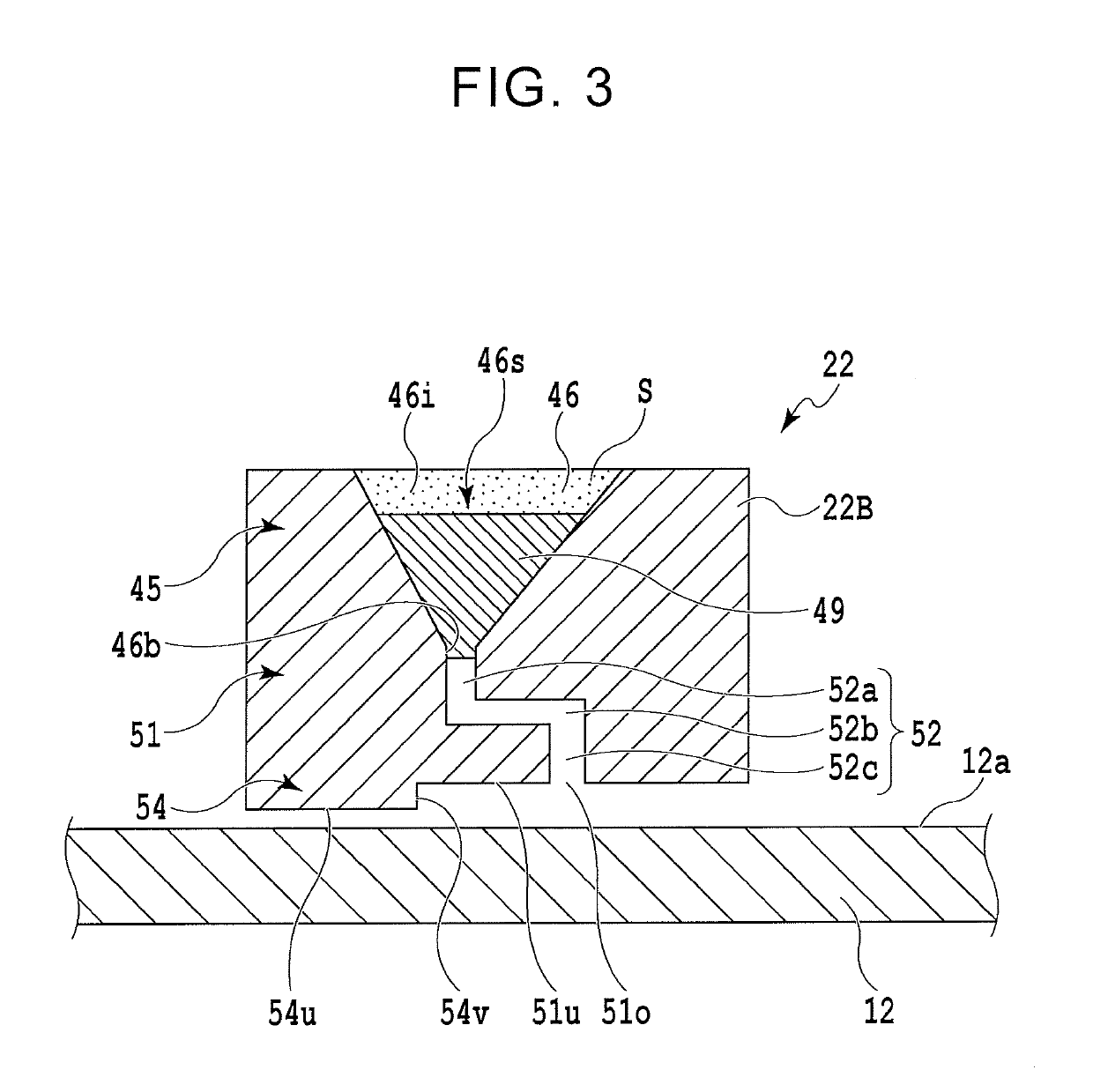
The three-dimensional molding device includes a recoater configured to discharge a granular material from a discharge port onto the molding table such that the granular material is superimposed in layer, a solidification device configured to solidify a partial region of the granular material in a plane solidification device direction of an upper surface of the molding table, a moving mechanism configured to cause the recoater to reciprocate in a plane direction parallel to the upper surface of the molding table, and at least one plug member configured to close a part of an opening in at least one location in a longitudinal direction of the discharge port of the recoater and limit a discharge range of the granular material.

Description

INCORPORATION BY REFERENCE[0001]The disclosure of Japanese Patent Application No. 2016-157955 filed on Aug. 10, 2016 including the specification, drawings and abstract is incorporated herein by reference in its entirety.BACKGROUND1. Technical Field[0002]The disclosure relates to a three-dimensional molding device and a three-dimensional molding method, which form a molded object by laminating and solidifying a granular material.2. Description of Related Art[0003]In solid object molding in recent years, by giving a three-dimensional object a structure where layered laminations are stacked, a three-dimensional molding device has been spreading, which performs a molding operation of such objects automatically. For example, WO 2015 / 151832 describes a three-dimensional molding device that repeats operations of spreading sand, which is a granular material, on a molding table, and solidifying and laminating the sand using a binder in a partial region corresponding to a solid-shaped transve...

Claims


Application Information

Patent Timeline
Patent Type & Authority Patents(United States)
IPC IPC(8): B29C64/165B29C64/205B29C64/255B33Y10/00B33Y30/00B29C64/153B29C64/393B29C64/214B33Y50/02
CPCB33Y10/00B29C64/165B29C64/255B29C64/393B29C64/214B33Y50/02B29C64/205B33Y30/00B29C64/153
Inventor IKEYAMA, KOICHIERA, NAOYA
Owner TOYOTA JIDOSHA KK
Learn More