Illuminator

a technology of illumination device and illumination plate, which is applied in the direction of fixed installation, lighting and heating apparatus, instruments, etc., can solve the problem of difficulty in achieving the emission of the entire surface on the front side of the illumination devi

Active Publication Date: 2015-12-03
PANASONIC INTELLECTUAL PROPERTY MANAGEMENT CO LTD
View PDF19 Cites 14 Cited by
  • Summary
  • Abstract
  • Description
  • Claims
  • Application Information

AI Technical Summary

Benefits of technology

[0020]Preferably, an area occupation ratio of the recesses and/or projections in the reflecting surface of the second light scatteri

Problems solved by technology

However, if the frame member 870 is attached to the outer periphery of the light guide plate 840, the frame member 870 blocks light emitted from the outer p

Method used


Image

  • Illuminator
  • Illuminator
  • Illuminator

Examples


first embodiment

Overall Structure

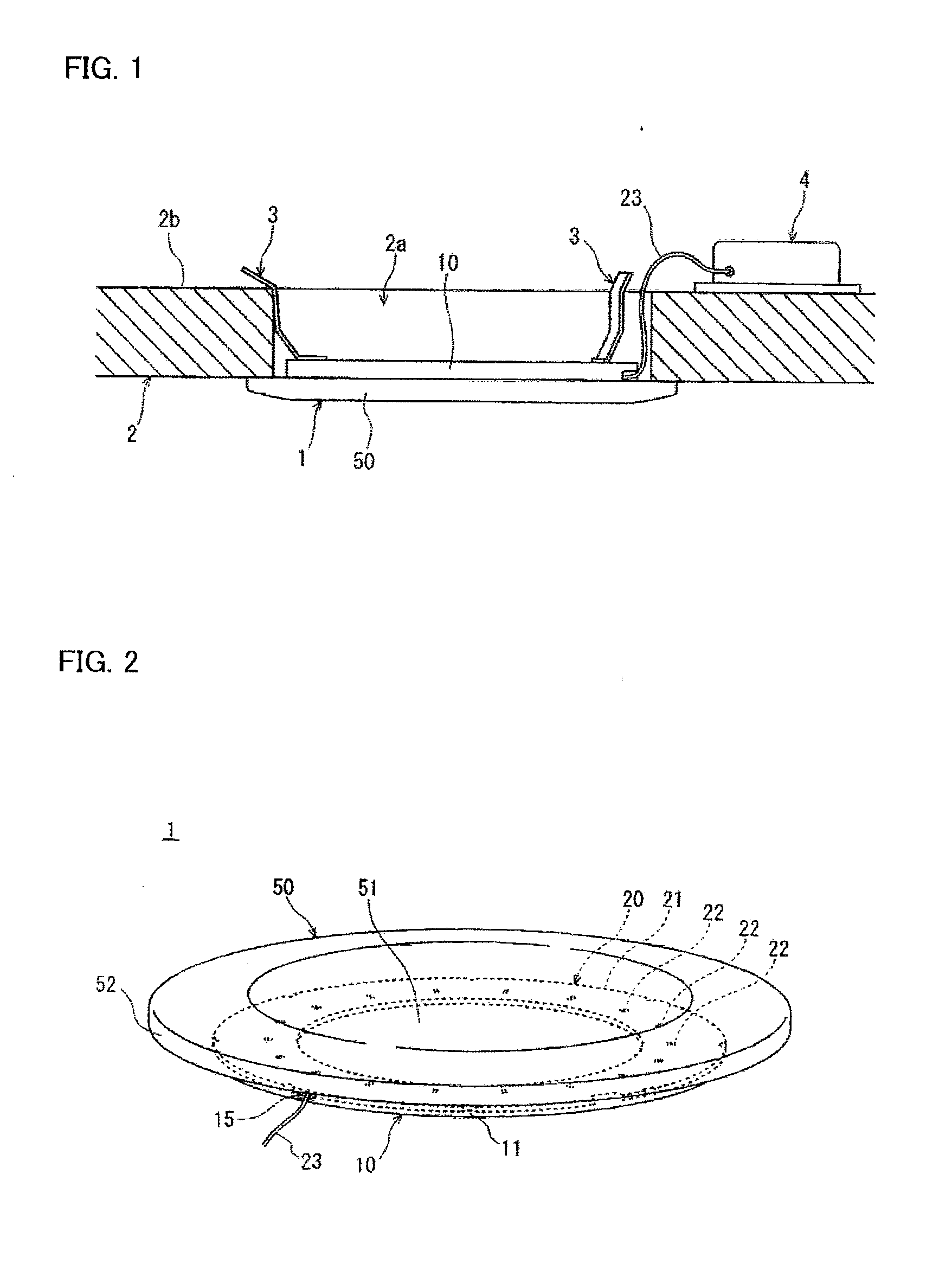
[0048]FIG. 1 is a view for explaining a mode of attaching an illumination device according to a first embodiment of the present invention to a ceiling plate. As shown in FIG. 1, the illumination device 1 according to an aspect of the present invention is, for example, a down light embedded in and attached to a ceiling plate 2. Note that the illumination device 1 according to the present invention is not limited to a down light, and can be an illumination device for a building other than the down light, such as a ceiling light, and can also be an illumination device other than the illumination device for a building such as a back light.

[0049]The illumination device 1 is attached to the ceiling plate 2 by inserting a part of a housing 10 into a through-hole 2a formed in the ceiling plate 2, and by allowing a leaf spring-like hook member 3 attached to the housing 10 to be hooked on a ceiling back surface 2b of the ceiling plate 2. Note that the hook member 3 is not lim...

second embodiment

[0114]FIG. 14 is an exploded perspective view of an illumination device according to a second embodiment. FIG. 15 is a cross-sectional view showing the illumination device according to the second embodiment. FIG. 16 is an enlarged cross-sectional view of a portion surrounded by a one-dot chain line shown in FIG. 15.

[0115]The illumination device 100 according to the second embodiment is much different from the illumination device 1 according to the first embodiment in that a reflecting member 30 comprises only an inner reflecting member 30a, and that a light guide plate 140 does not comprise an annular outer part. Since it has many similarities to the illumination device 1 according to the first embodiment, only the differences between the two will be described, and the same reference numerals are used for the common structure, and a description thereof is omitted.

[0116]As shown in FIG. 14 to FIG. 16, the illumination device 100 comprises, for example, a housing 110, a light emitting...

modified example

[0136]Hereinafter, a modified example of an illumination device according to the present invention will be described. FIG. 17 is a cross-sectional view for explaining a light guide plate and a reflecting member according to the modified example.

(Reflecting Member)

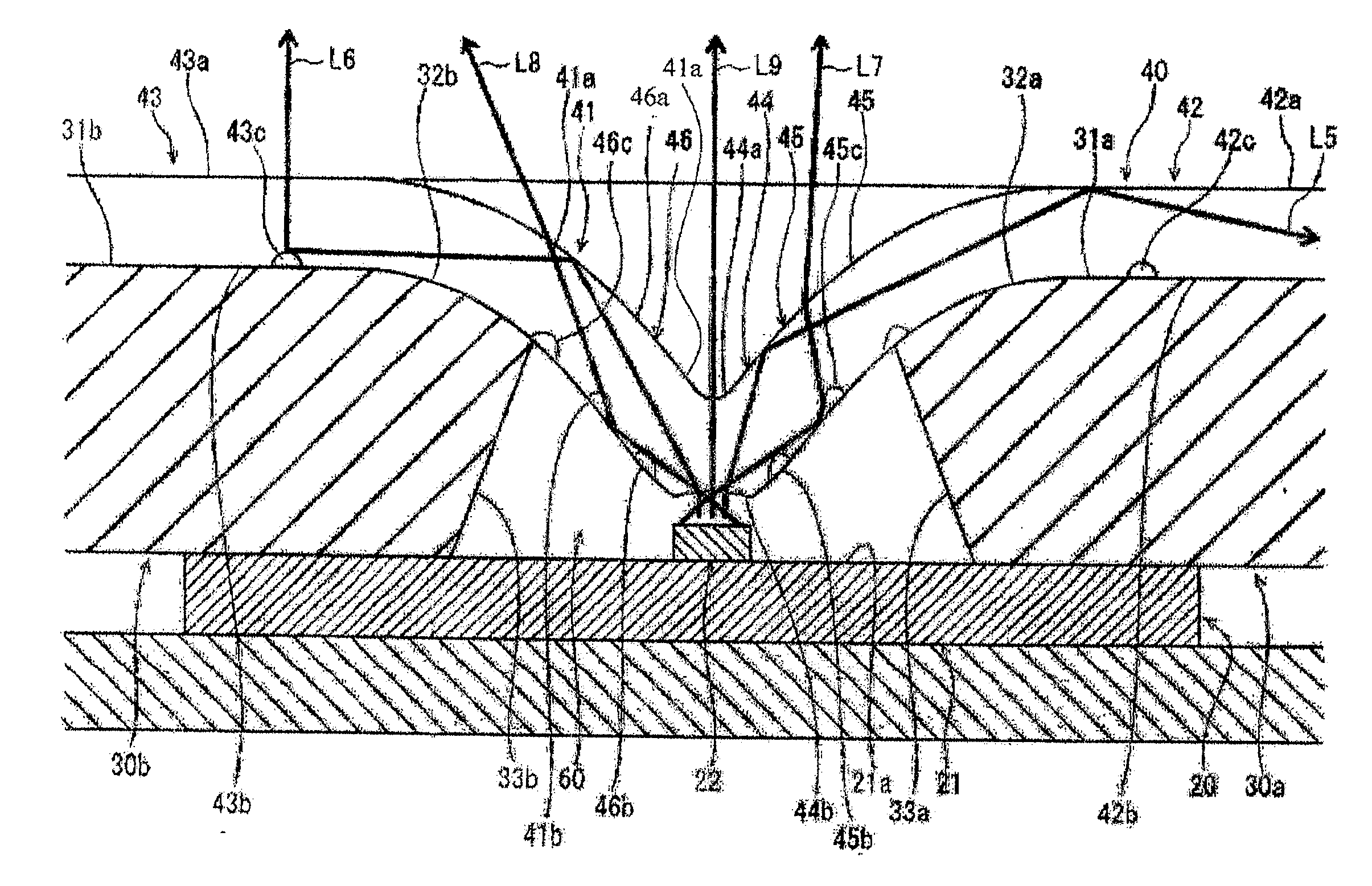
[0137]In the first embodiment, the angle θ1 between the element mounting surface 21a of the substrate 21 and the outer peripheral surface 33a of the inner reflecting member 30a is an acute angle. However, as shown in FIG. 17, the angle θ1 between the element mounting surface 21a of the substrate 21 and an outer peripheral surface 233a of an inner reflecting member 230a can be a right angle or an obtuse angle. Further, in the first embodiment, the angle θ2 between the element mounting surface 21a of the substrate 21 and the inner peripheral surface 33b of the outer reflecting member 30b is an acute angle. However, as shown in FIG. 17, the angle θ2 between the element mounting surface 21a of the substrate 21 and an inner peri...


PUM


Abstract

A light guide plate 40 comprises: an annular part 41 formed in an annular shape along an element array of multiple light emitting elements 22; and an annular inner part 42 formed on an annular inside of the annular part 41 continuously with the annular part 41. The annular part 41 comprises: an element array-facing part 44 which is a part facing the element array and which has an incident surface 44b to allow light emitted from the light emitting elements 22 to enter; and a first reflecting part 45 which is a part located closer to the annular inner part than the element array-facing part 44, and which has a reflecting surface for reflecting the light entering from the incident surface 44b toward the annular inner part 42. The first reflecting part 45 comprises a first light scattering region 45b having a light scattering treatment applied thereto.

Description

TECHNICAL FIELD[0001]The present invention relates to an illumination device having light emitting elements such as LEDs (Light Emitting Diodes) as a light source, and particularly relates to a technology for reducing luminance unevenness in an illumination device for surface emission using a light guide plate.BACKGROUND ART[0002]An example of an illumination device for surface emission using a light guide plate is an edge light type illumination device 800 as shown in FIG. 18 (refer to Patent Document 1). FIG. 18 shows a plan view of the illumination device 800. In the illumination device 800, multiple light emitting elements 822 are annularly arranged around an outer periphery of a light guide plate 840 with their respective main emission directions directed to the light guide plate 840. Light emitted from the light emitting elements 822 enters the light guide plate 840 from an incident surface 840c which is an outer peripheral surface of the light guide plate 840, and is emitted ...

Claims


Application Information

Patent Timeline
IPC IPC(8): F21V8/00
CPCG02B6/0045G02B6/0016F21S8/04F21S8/02F21Y2105/00F21Y2115/10G02B6/002G02B6/0043G02B6/0055G02B6/0001F21V2200/00
Inventor KADORIKU, SHINJIMURASE, RYOMA
Owner PANASONIC INTELLECTUAL PROPERTY MANAGEMENT CO LTD
Why Eureka
Try Eureka