

Rear attachment lens
a rear attachment and lens technology, applied in the field of rear attachment lenses, can solve the problems of insufficient correction of longitudinal chromatic aberration to cope with an increase in pixel numbers, and achieve the effects of increasing the focal length of an entire lens system, excellent correction, and high optical performan
- Summary
- Abstract
- Description
- Claims
- Application Information
AI Technical Summary
Benefits of technology
Problems solved by technology
Method used
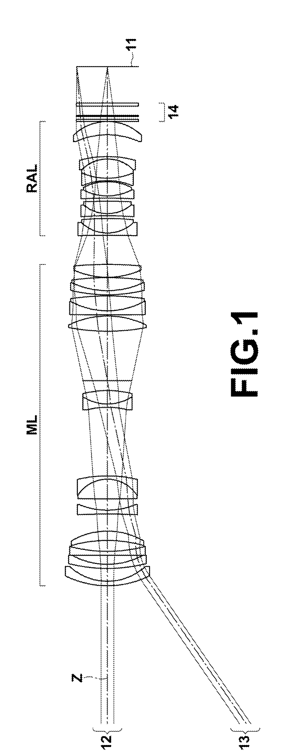
Image

Examples
example 1
[0075]FIG. 3 is a diagram illustrating the configuration of a rear attachment lens in Example 1. Since the lens configuration of the rear attachment lens in Example 1 has been described already, redundant explanation will be omitted here. Table 3 shows basic lens data of the rear attachment lens in Example 1 and an optical member 14. The signs and the description method used in Table 3 are basically similar to those used in Table 1. Table 4 shows maximum image height LH, focal length f, back focus Bf, F-number FNo., maximum full angle 2ω of view in a state of being focused on an object at infinity, a ratio of increasing magnification, and a distance between a main lens and a rear attachment lens (a length on an optical axis from a lens surface closest to the image side in the main lens to a lens surface closest to the object side in the rear attachment lens), as the specification of a lens system in which the rear attachment lens in Example 1 has been attached to the image side of t...
example 2
[0078]FIG. 4 is a diagram illustrating the configuration of a rear attachment lens in Example 2. In FIG. 4, the optical member 14 is also illustrated. The schematic configuration of the rear attachment lens in Example 2 is similar to that of Example 1. Table 5 shows basic lens data of the rear attachment lens in Example 2 and the optical member 14. Table 6 shows the specification of a lens system in which the rear attachment lens in Example 2 and the optical member 14, shown in Table 5, are attached to the image side of the main lens. FIG. 8 illustrates aberration diagrams of this lens system.
TABLE 5EXAMPLE 2SiRiDiNdjνdjθgFj13072.936911.3671.5377574.700.53936217.312146.6301.5317248.840.563093−157.200161.2504−202.642251.0102.0010029.130.59952516.216345.5611.7552027.510.610336−946.897062.6127−174.696361.0102.0010029.130.59952823.245476.5591.5927035.310.593369−23.245470.37510−29.078381.1101.7129953.870.545871129.078389.0741.5927035.310.5933612−16.020981.1001.8040046.580.5573013−42.2789...
example 3
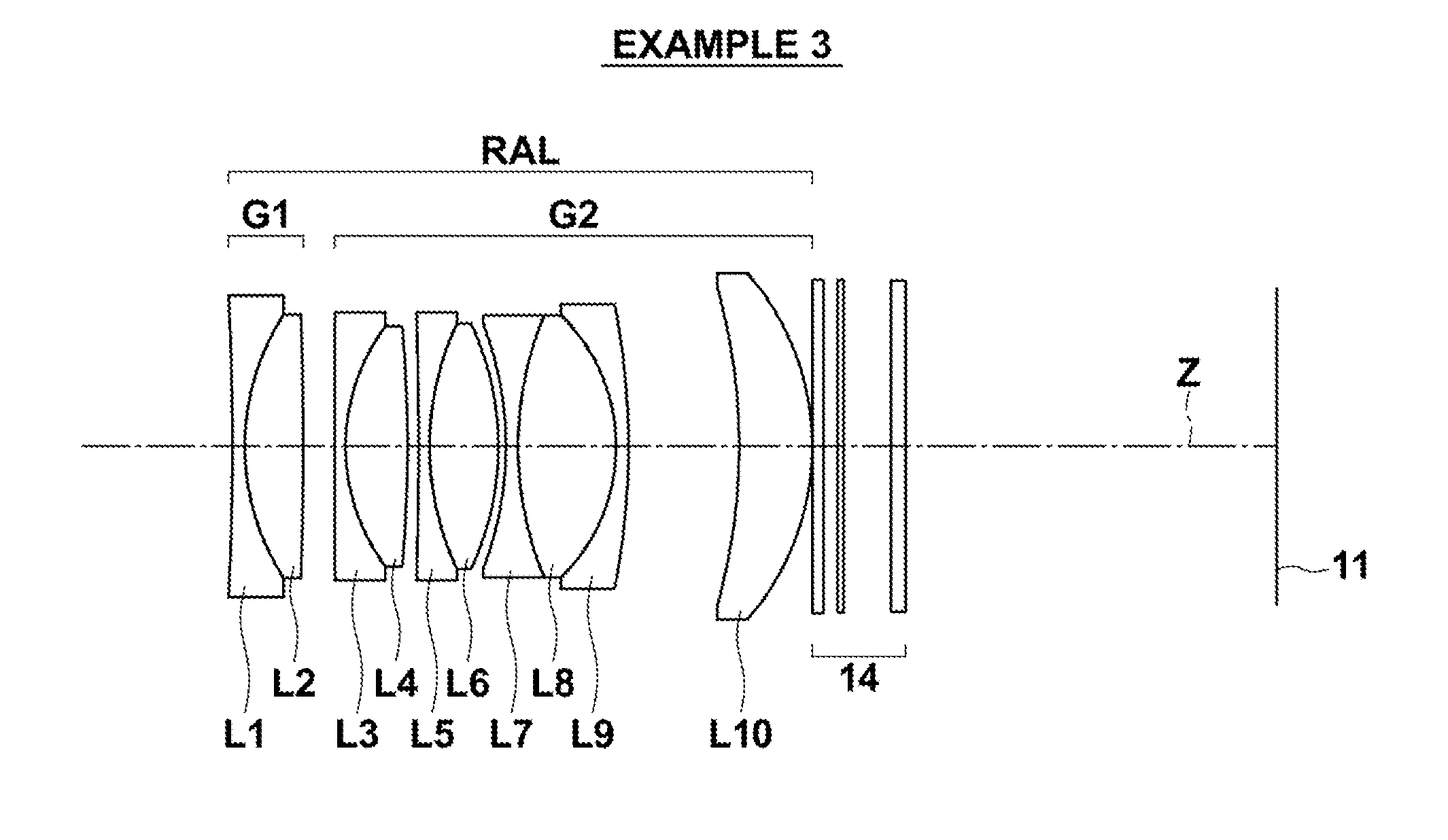
[0079]FIG. 5 is a diagram illustrating the configuration of a rear attachment lens in Example 3. In FIG. 5, the optical member 14 is also illustrated. The schematic configuration of the rear attachment lens in Example 3 is similar to that of Example 1. Table 7 shows basic lens data of the rear attachment lens in Example 3 and the optical member 14. Table 8 shows the specification of a lens system in which the rear attachment lens in Example 3 and the optical member 14, shown in Table 7, are attached to the image side of the main lens. FIG. 9 illustrates aberration diagrams of this lens system.
TABLE 7EXAMPLE 3SiRiDiNdjνdjθgFj1−251.829091.1101.5928268.630.54414221.578235.2621.5673242.820.573093−320.498522.83042780.879021.0102.0010029.130.59952517.893985.5581.5927035.310.593366−124.904831.0007−441.968151.0101.9108235.250.58224825.698116.1991.5927035.310.593369−25.698110.67910−30.512061.1101.7129953.870.545871130.512068.8461.5927035.310.5933612−16.347481.1021.8040046.580.5573013−66.0074...
PUM
 Abstract
Description
Claims
Application Information