Method for ascertaining distortion properties of an optical system in a measurement system for microlithography

a technology of optical system and distortion property, which is applied in the direction of photomechanical apparatus, printers, instruments, etc., can solve the problem of structure-dependent deformation of image field, and achieve the effect of accurate determination or specification of optical system properties

Active Publication Date: 2015-12-03
CARL ZEISS SMT GMBH
View PDF4 Cites 6 Cited by
  • Summary
  • Abstract
  • Description
  • Claims
  • Application Information

AI Technical Summary

Benefits of technology

[0024]As a result, the invention enables the more accurate determination or specification of properties of an optical system to the effect that a correct separation or differentiation of field-dependent image aberrations and image aberrations on account of geometrical distortion is obtained.

Problems solved by technology

These field-dependent image aberrations lead to a structure-dependent deformation of the image field.

Method used


Image

  • Method for ascertaining distortion properties of an optical system in a measurement system for microlithography
  • Method for ascertaining distortion properties of an optical system in a measurement system for microlithography
  • Method for ascertaining distortion properties of an optical system in a measurement system for microlithography

Examples


Embodiment Construction

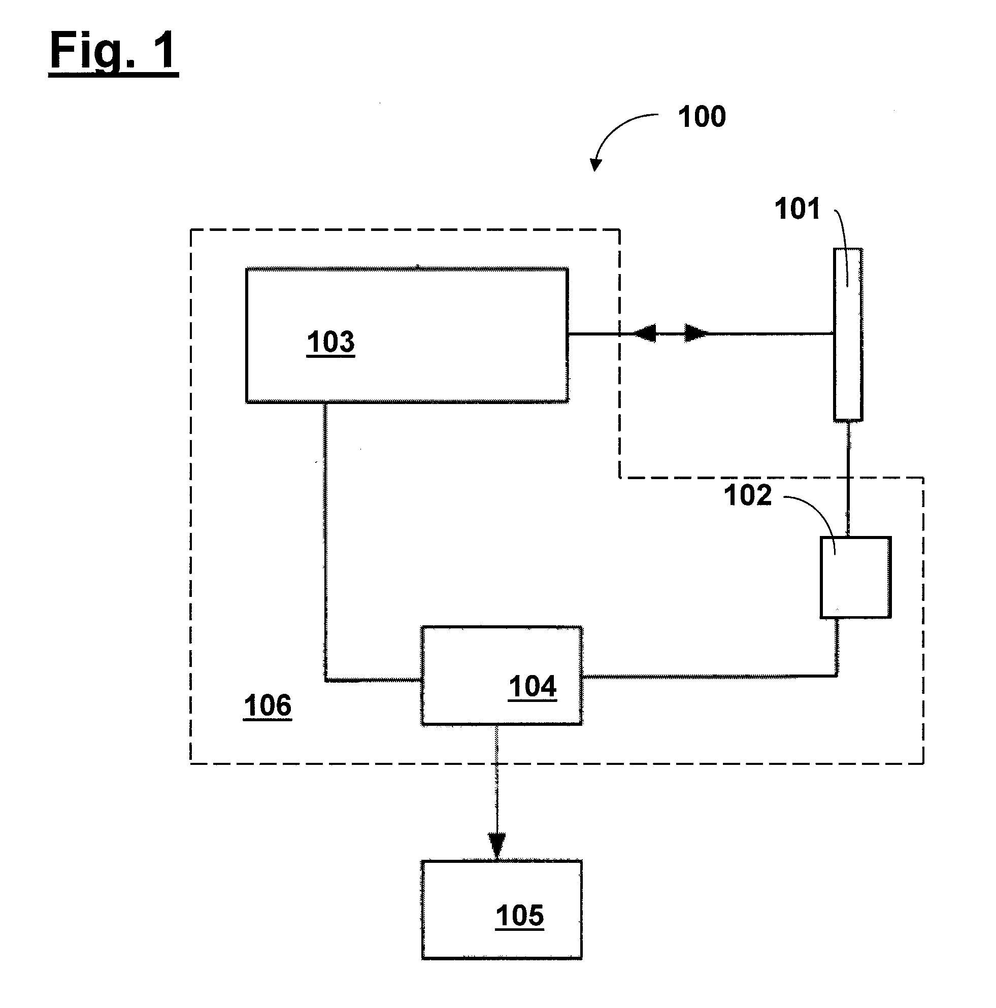
[0037]Firstly, for elucidating one possible application of the invention, the construction of a position measurement system suitable for determining the measured aerial image is described below with reference to the schematic illustration in FIG. 1. The position measurement system 100 in accordance with FIG. 1 comprises a recording device 106 having a positioning device 102 serving for setting the position of a lithography mask 101, an optical system 103, by which segments of the lithography mask 101 can be recorded in a magnified fashion, and also a control device 104. The position measurement system 100 in accordance with FIG. 1 furthermore comprises an evaluation device 105. The image data of the recordings generated by the recording device 106 are fed to the control device 104, which forwards the data to the evaluation device 105. By using the position measurement system 100, a measurement image (in the form of a first aerial image) of a segment of the lithography mask 101 is re...


PUM

PropertyMeasurementUnit
optical systemaaaaaaaaaa
optical forward simulationaaaaaaaaaa
phase measurementaaaaaaaaaa

Abstract

A method for ascertaining distortion properties of an optical system in a measurement system for microlithography is provided, wherein the optical system images at least one structure to be measured into a measurement image. In accordance with one aspect, a method according to the invention comprises the following steps: measuring the field-dependent image aberrations of the optical system; determining a first distortion pattern present in the first image field generated by the optical system during measurement of at least one predefined structure; carrying out an optical forward simulation for the predefined structure taking account of the field-dependent image aberrations measured previously, with a second image field being generated; determining a second distortion pattern for the second image field generated previously; and ascertaining the structure-independent distortion properties of the optical system by calculating a third distortion pattern as the difference between the first distortion pattern and the second distortion pattern.

Description

CROSS REFERENCE TO RELATED APPLICATIONS[0001]This application is a continuation of PCT application PCT / EP2014 / 052776, filed on Feb. 13, 2014, which claims priority to German patent application DE 10 2013 101 445.3 and U.S. provisional patent application 61 / 764,815, both filed on Feb. 14, 2013. The entire contents of the above applications are herein incorporated by reference.BACKGROUND OF THE INVENTION[0002]1. Field of the invention[0003]The invention relates to a method for ascertaining distortion properties of an optical system in a measurement system for microlithography.[0004]2. Prior art[0005]Microlithography is used for producing microstructured components, such as integrated circuits or LCDs, for example. The microlithography process is carried out in a so-called projection exposure apparatus comprising an illumination device and a projection lens. The image of a mask (also referred to as a reticle) illuminated by the illumination device is in this case projected by the proje...

Claims


Application Information

Patent Timeline
Patent Type & Authority Applications(United States)
IPC IPC(8): G03F7/20
CPCG03F7/70433G01B11/02G03F1/84G03F7/70616G01N2021/95676G03F7/70483G03F7/70425G03F7/706G03F7/70525G03F7/705G03F7/70666G03F7/70625
Inventor SEIDEL, DIRKTOEPFER, SUSANNEHIMMELHAUS, MICHAEL
Owner CARL ZEISS SMT GMBH
Why Eureka
Try Eureka