System and Method for Determining Heat and Fluid Flow in or Around Objects

a technology of heat and fluid flow and system, applied in the direction of instruments, computation using non-denominational number representation, design optimisation/simulation, etc., can solve the problems of different models and algorithms, and current computer modeling schemes have proven limited in the form of objects they can model

Inactive Publication Date: 2015-12-03
UNIVERSITY OF WINDSOR
View PDF2 Cites 11 Cited by
  • Summary
  • Abstract
  • Description
  • Claims
  • Application Information

AI Technical Summary

Benefits of technology

[0012]In yet a further alternate embodiment, the system and method provide for analysis and modeling of combinations of dynamic internal and external flows, such as air flow around moving road vehicles, and air flow around an aircraft du

Problems solved by technology

Current computer modeling schemes have proven limited in the form of objects they can model and require different models and algori

Method used


Image

  • System and Method for Determining Heat and Fluid Flow in or Around Objects
  • System and Method for Determining Heat and Fluid Flow in or Around Objects
  • System and Method for Determining Heat and Fluid Flow in or Around Objects

Examples


Embodiment Construction

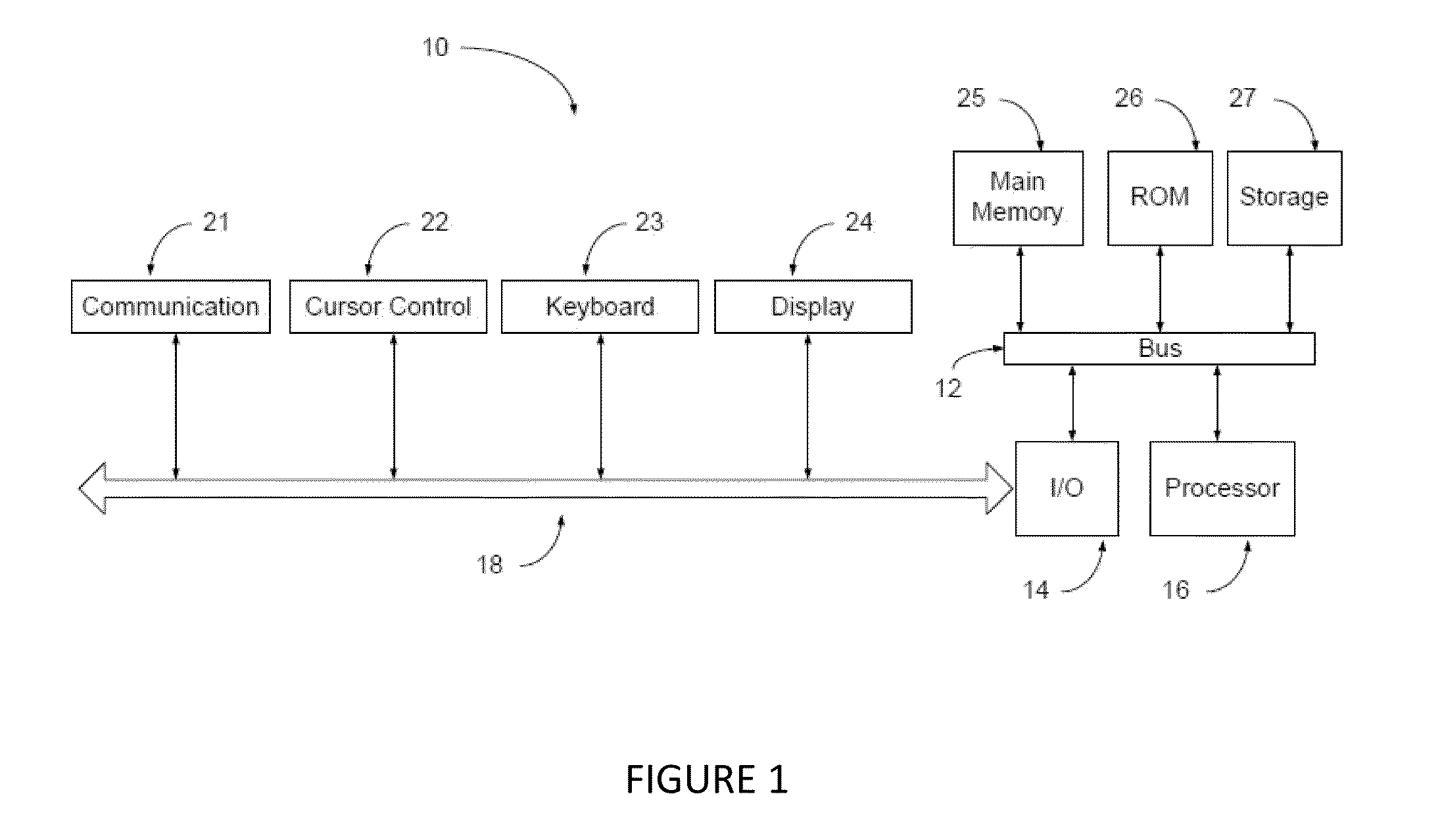
[0072]FIG. 1 illustrates schematically a system 10 for determining or the predicted modelling of compressible and non-compressible fluids in accordance with a preferred embodiment of the invention. The system 10 includes a computer which includes main memory 25, read only memory 26, and storage memory 27. A bus 12 provides electronic communication between the main memory 25 ROM, 26 and storage memory 27, and the computer processor 16 and I / O board 14.

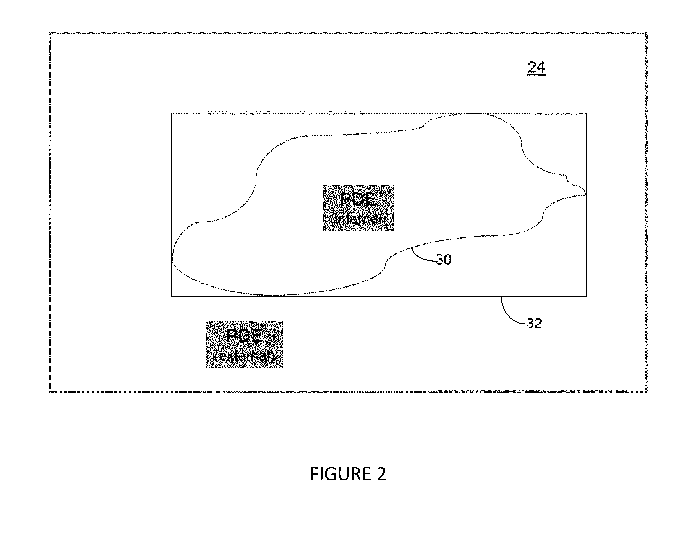
[0073]The I / O board 14 communicates via a suitable data connector 18 with the user operable keyboard 23, video display 24 and cursor control 22. In addition secondary communication output 21 may also be provided. The processor 16 stores computer program instructions which in operation of the system 10 are adapted to provide and output to a user a graphic and / or data output on the display 24, which simulates fluid flow dynamics through and / or around physical boundary defining target object 30 (see for example FIG. 2).

[0074]As will be des...


PUM


Abstract

A system includes a processor with stored instructions for generating a Cartesian mesh model of a bounded or unbounded object domain. The model includes active, inactive and boundary nodes which encompass the domain. The processor effects of discretizing a partial differential equation based on a stencil associated with each active node in the mesh by (i) selecting an active node, (ii) identifying the stencil associated with the selected node, (iii) mapping the stencil from the physical domain to a generic uniform computational stencil, (iv) applying finite difference formulas on the computational stencil to approximate the partial differential equation by a finite difference equation, (v) solving the finite difference equation to obtain an approximate value for the solution, and thereafter (vi) checking the iteration process for convergence. If the solution has not converged, the system repeats the aforementioned steps, or terminates the iteration process if the solution has converged, and outputs to a user the calculated data file.

Description

RELATED APPLICATIONS[0001]This application claims the benefit under 35 USC §119(e) to U.S. Provisional Application No. 62 / 006,556, filed on Jun. 2, 2014, the contents of which are hereby incorporated by reference in their entirety.FIELD OF THE INVENTION[0002]This invention relates to a system and method for modeling physical phenomena such as internal conditions and / or boundary conditions, as for example to model or determine fluid flows in, around and / or across objects or structures and, in particular, a system and method which operates to provide a numerical solution of partial differential equations (PDEs).BACKGROUND OF THE INVENTION[0003]Computer methods and algorithms which use partial differential equations to analyze and solve complex systems involving various forms of fluid dynamics having input boundary conditions are known. Computer modeling may allow a user to simulate the flow of air and other gases over an object or model the flow of fluid through a pipe. Computational ...

Claims


Application Information

Patent Timeline
IPC IPC(8): G06F17/50G06F17/13
CPCG06F17/13G06F17/5018G06F30/23
Inventor BARRON, RONALD
Owner UNIVERSITY OF WINDSOR
Why Eureka
Try Eureka