
Improved split field time domain finite difference algorithm

A time domain finite difference and split field technology, applied in computing, complex mathematical operations, instruments, etc., can solve problems such as memory consumption and time consumption, and achieve the effect of reducing memory usage and fast computing time

Active Publication Date: 2019-12-20
NANJING UNIV OF SCI & TECH
View PDF2 Cites 0 Cited by
  • Summary
  • Abstract
  • Description
  • Claims
  • Application Information

AI Technical Summary

Problems solved by technology

However, the traditional split-field time-domain finite difference algorithm needs to calculate the two variables introduced to eliminate the phase difference every half time step, which not only consumes memory but also consumes time.

Method used


Image

  • Improved split field time domain finite difference algorithm
  • Improved split field time domain finite difference algorithm
  • Improved split field time domain finite difference algorithm

Examples


Embodiment

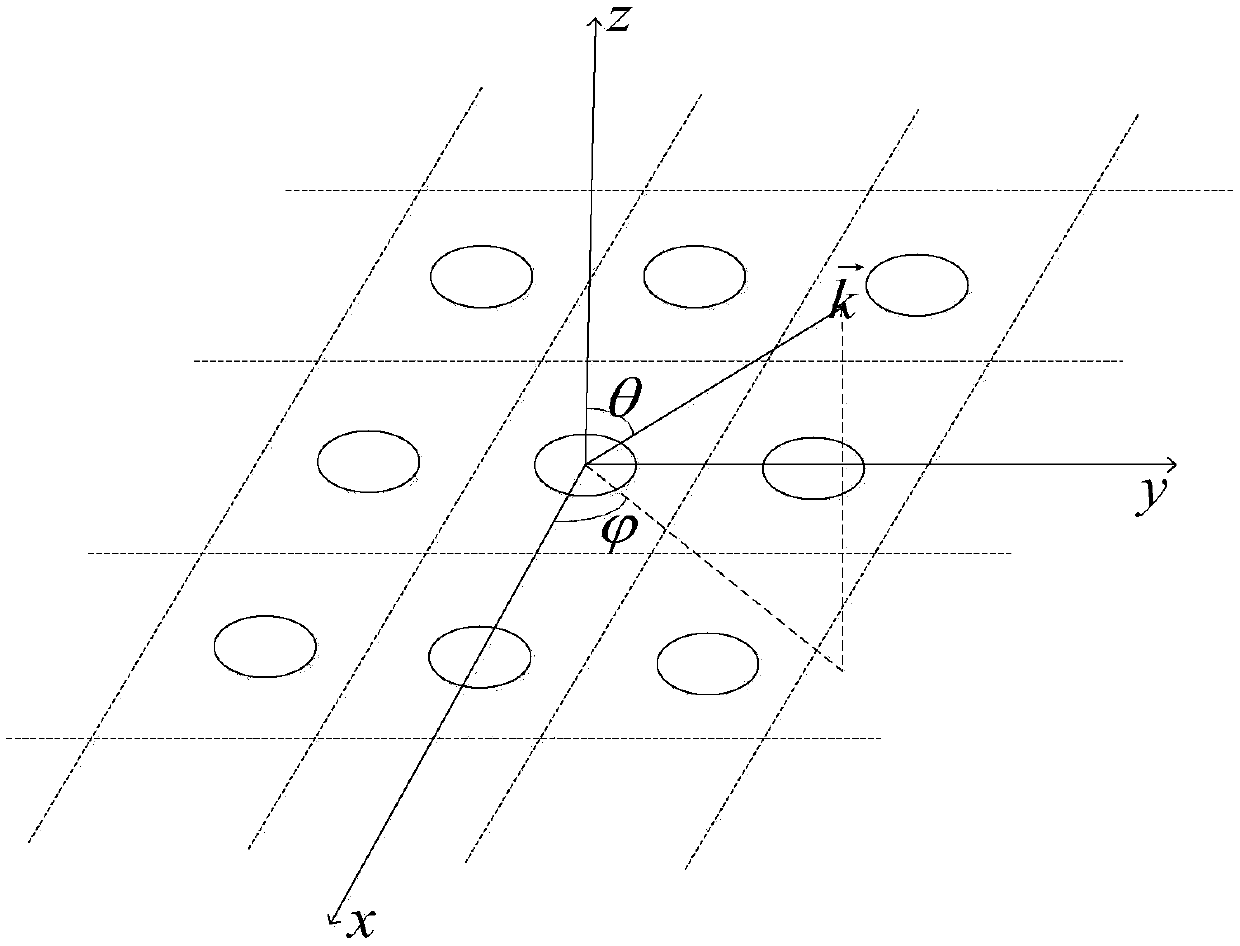
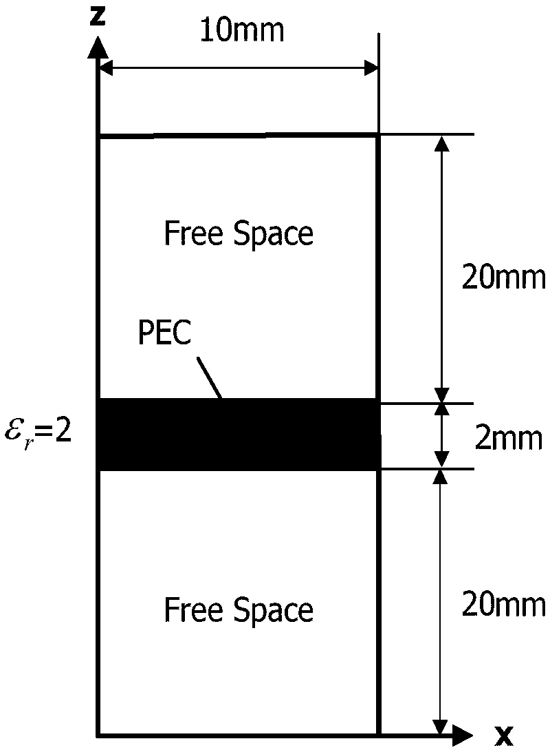
[0047] The frequency selective surface (FSS) is shown in Fig. 3(a) and Fig. 3(b). The dielectric parameter ε of the medium r = 2, a metal patch is placed in the middle, the incident wave is a modulated Gaussian pulse, the center frequency is 15GHz, and the calculation frequency range is 6-20GHz; the subdivision size of the Yee cell is △x=△y=△z=0.25mm, PML layer Set to 20 layers, the total number of grids is 40×40×106, and calculate the reflection coefficient when the incident angle of the plane wave deviates from the z-axis direction by 30°. Figure 4 The method proposed by the present invention is compared with the calculation results of the traditional split-field time-domain finite difference algorithm, and table 1 counts the calculation results of the method proposed by the present invention and the traditional split-field time-domain finite-difference algorithm under the same iteration time. Consumption time and memory comparison.

[0048] Table 1. Computational time an...


PUM


Abstract

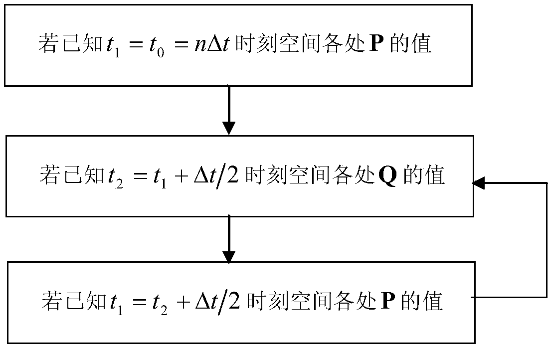
The invention discloses an improved split field time domain finite difference algorithm, which comprises the following steps: replacing a vector electric field E and a vector magnetic field H with vectors P and Q in Maxwell, and establishing a split field time domain finite difference equation; calculating a'a 'component value and a'b' component value of the n delta < t > integer moment vector P;calculating a'a 'component value and a'b' component value of the (n + 1 / 2) delta t semi-integer moment vector Q; and detecting whether the calculation of the set time step is completed or not, if so,stopping the calculation, and if not, circulating the steps. According to the method, in a traditional split field time domain finite difference algorithm, mean value approximate difference is directly used for a split field, in this way, alternate iteration only needs to be conducted on new variables of an introduced electric field and an introduced magnetic field every half time step, and not only can the memory be saved, but also the calculation time can be saved.

Description

technical field [0001] The invention relates to a fast calculation technology of electromagnetic characteristics of a periodic target, in particular to an improved split field time domain finite difference algorithm. Background technique [0002] With the deepening of research in the field of computational electromagnetics, periodic structures have been widely used in many electromagnetic application fields of finite-difference time-domain algorithms, such as frequency selective surfaces (FSS), periodic array antennas, random rough surfaces, etc. [0003] When plane waves are obliquely incident, there is a phase delay in the electromagnetic field space, and there are field values ​​at future time instants when periodic boundary conditions are used. Therefore, many scholars widely use the split-field finite difference time domain algorithm to solve the phase delay problem. However, the traditional split-field time-domain finite difference algorithm needs to calculate every ha...

Claims


Application Information

Patent Timeline
Patent Type & Authority Applications(China)
IPC IPC(8): G06F17/50G06F17/14
CPCG06F17/14Y02E60/00
Inventor 盛亦军李燕茹陈如山马立宪丁大志樊振宏
Owner NANJING UNIV OF SCI & TECH
Learn More