System and Method for Detecting Features in Aerial Images Using Disparity Mapping and Segmentation Techniques

a technology of disparity mapping and segmentation techniques, applied in image enhancement, instruments, image data processing, etc., can solve the problems of system inability to improve, system time-consuming and difficult to use, and a large amount of manual input by users, so as to achieve efficient over time

Active Publication Date: 2015-12-03
XACTWARE SOLUTIONS
View PDF3 Cites 93 Cited by
  • Summary
  • Abstract
  • Description
  • Claims
  • Application Information

AI Technical Summary

Benefits of technology

[0008]The present system of the current disclosure detects features in aerial images using disparity mapping and segmentation techniques. More specifically, the system includes an object detection pre-processing engine for object detection and classification using one or more aerial images. The object detection pre-processing engine includes disparity map generation, segmentation, and classification to identify various objects and types of objects in an aerial image. Detection algorithms, including region growing algorithms and split-and-merge segmentation algorithms, are applied to an image to identify structures. These component-based algorithms can evolve and become more efficient over time. The information derived from these pre-processed images can then be used by the mass production engine for the manual and / or automated production of drawings, sketches, and models. A quality control engine could also be used for ensuring the accuracy of any drawings, sketches, or models generated by the system.

Problems solved by technology

However, such systems are often time-consuming and difficult to use, and require a great deal of manual input by a user.
Further, such systems may not have the ability to improve results through continued usage over time.

Method used


Image

  • System and Method for Detecting Features in Aerial Images Using Disparity Mapping and Segmentation Techniques
  • System and Method for Detecting Features in Aerial Images Using Disparity Mapping and Segmentation Techniques
  • System and Method for Detecting Features in Aerial Images Using Disparity Mapping and Segmentation Techniques

Examples


Embodiment Construction

[0036]The present disclosure relates to a system and method for detecting features in aerial images using disparity mapping and segmentation techniques, as discussed in detail below in connection with FIGS. 1-28.

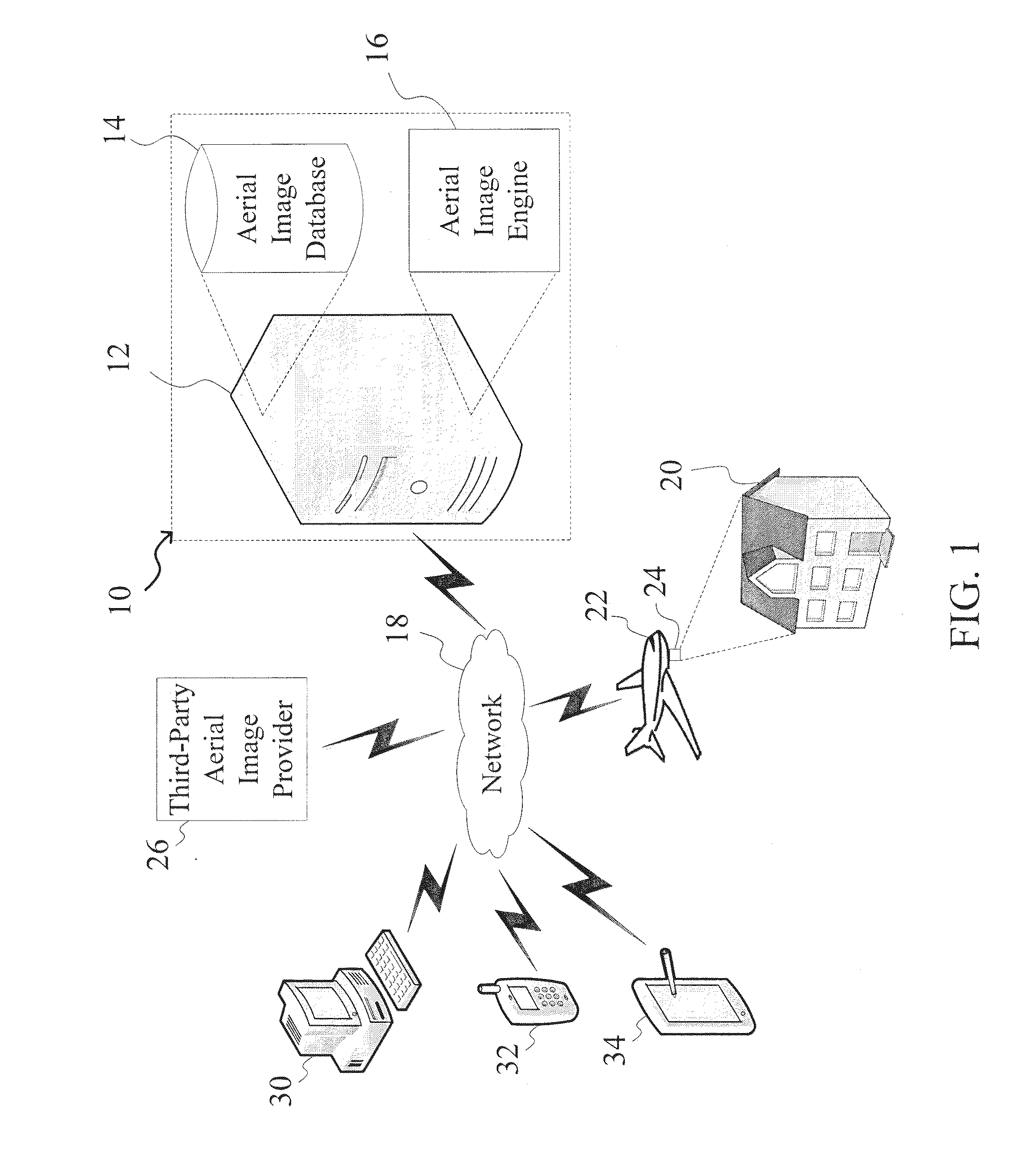
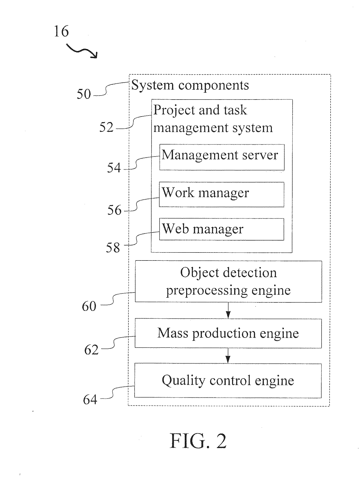
[0037]FIG. 1 is a diagram showing the system of the present disclosure for detecting features in aerial images, indicated generally at 10. The system 10 comprises a computer system 12 (e.g., a server) having an aerial image database 14 stored therein and a software aerial image engine (module) 16. The database 14 could be stored on the computer system 12, or located externally (e.g., in a separate database server in communication with the system 10). As will be discussed in greater detail below, the aerial image engine 16 allows users to detect features in aerial images and generate three-dimensional models therefrom.

[0038]The system 10 can communicate through a network 18 with one or more of a variety of image providers to obtain aerial images or photographs of a building s...


PUM


Abstract

A system for aerial image detection and classification is provided herein. The system comprising_an aerial image database storing one or more aerial images electronically received from one or more image providers, and an object detection pre-processing engine in electronic communication with the aerial image database, the object detection pre-processing engine detecting and classifying objects using a disparity mapping generation sub-process to automatically process the one or more aerial images to generate a disparity map providing elevation information, a segmentation sub-process to automatically apply a pre-defined elevation threshold to the disparity map, the pre-defined elevation threshold adjustable by a user, and a classification sub-process to automatically detect and classify objects in the one or more stereoscopic pairs of aerial images by applying one or more automated detectors based on classification parameters and the pre-defined elevation threshold.

Description

CROSS-REFERENCE TO RELATED APPLICATIONS[0001]This application claims priority to U.S. Provisional Patent Application No. 61 / 861,610 filed on Aug. 2, 2013, the entire disclosure of which is expressly incorporated herein by referenceBACKGROUND[0002]1. Field of the Disclosure[0003]The present disclosure relates generally to the field of aerial image detection and classification. More specifically, the present disclosure relates to a system and method for detecting features in aerial images using disparity mapping and segmentation techniques.[0004]2. Related Art[0005]Accurate and rapid identification and estimation of objects in aerial images is increasingly important for a variety of applications. For example, roofing information is often used by construction professionals to specify materials and associated costs for both newly-constructed buildings, as well as for replacing and upgrading existing structures. Further, in the insurance industry, accurate information about construction ...

Claims


Application Information

Patent Timeline
Patent Type & Authority Applications(United States)
IPC IPC(8): G06K9/62G06T7/00G06K9/00H04N13/00G06V10/25
CPCG06K9/6292H04N13/0022G06T7/0075G06T7/0081G06K9/00637H04N2013/0081G06T2207/20141G06T2207/10021G06T2207/10032G06T2207/20148G06T2207/30184G06T2207/10028H04N2013/0092G01C11/06G06T7/593G06T7/11G06T7/187G06T7/136H04N13/128G06V20/64G06V10/25G06V20/176G06F18/254
Inventor TAYLOR, JEFFREYWEBECKE, EDMUND
Owner XACTWARE SOLUTIONS
Why Eureka
Try Eureka