
Circuit breaker

a circuit breaker and circuit technology, applied in the field of circuit breaker, can solve the problems of increased temperature in response to the flow of current, user injury, and mal-function of the circuit breaker, and achieve the effect of preventing an increase in temperature within a limited space and increasing costs

Active Publication Date: 2015-12-03
LSIS CO LTD
View PDF4 Cites 11 Cited by
  • Summary
  • Abstract
  • Description
  • Claims
  • Application Information

AI Technical Summary

Benefits of technology

The technical effect of the patent is to create a circuit breaker that can prevent temperatures from rising too high in a limited space without increasing costs.

Problems solved by technology

However, in the related art circuit breaker, while a current normally flows, temperature increases in response to the flow of the current.
When the temperature excessively increases, a mal-function of the circuit breaker may be caused or a user may be hurt.
However, it may result in an increase in fabricating costs and a limitation of an installation space.

Method used


Image

  • Circuit breaker
  • Circuit breaker
  • Circuit breaker

Examples


Embodiment Construction

[0035]Description will now be given in detail of preferred embodiments according to the present invention, with reference to the accompanying drawings.

[0036]Prior to explaining the preferred embodiments of the present invention, on the basis of FIG. 3, a left direction refers to a front side, a right direction refers to a rear side, front and rear directions in the drawings refer to sides, an upper direction refers to an upper side, and a lower direction refers to a lower side.

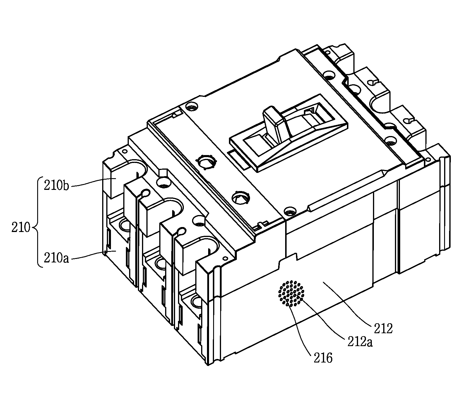
[0037]FIG. 3 is an exploded perspective view of a circuit breaker in accordance with one exemplary embodiment disclosed herein, FIG. 4 is a sectional view taken along the line II-II, which illustrates an inner structure of the circuit breaker of FIG. 3 after being assembled, FIG. 5 is a perspective view illustrating a radiation path of the circuit breaker of FIG. 3, FIG. 6 is a sectional view taken along the line III-III of FIG. 5, and FIG. 7 is a perspective view illustrating a movable contactor and a sliding...


PUM


Abstract

A circuit breaker according to the present invention includes a terminal switching unit mounted in an enclosure thereof, and the terminal switching unit accommodates, in a base as an outer casing thereof, a fixed contactor and a movable contactor contactable with and separated from each other, a sliding unit rotatably supporting the movable contactor, and a detection mechanism to detect a fault current. Radiators are provided at side portions of at least one of a contact portion where the movable contactor comes in contact with the fixed contactor, the sliding unit and the detection mechanism, each radiator radiating heat to the outside of the base. This may prevent an increase in temperature of the circuit breaker within a limited space without an increase in costs.

Description

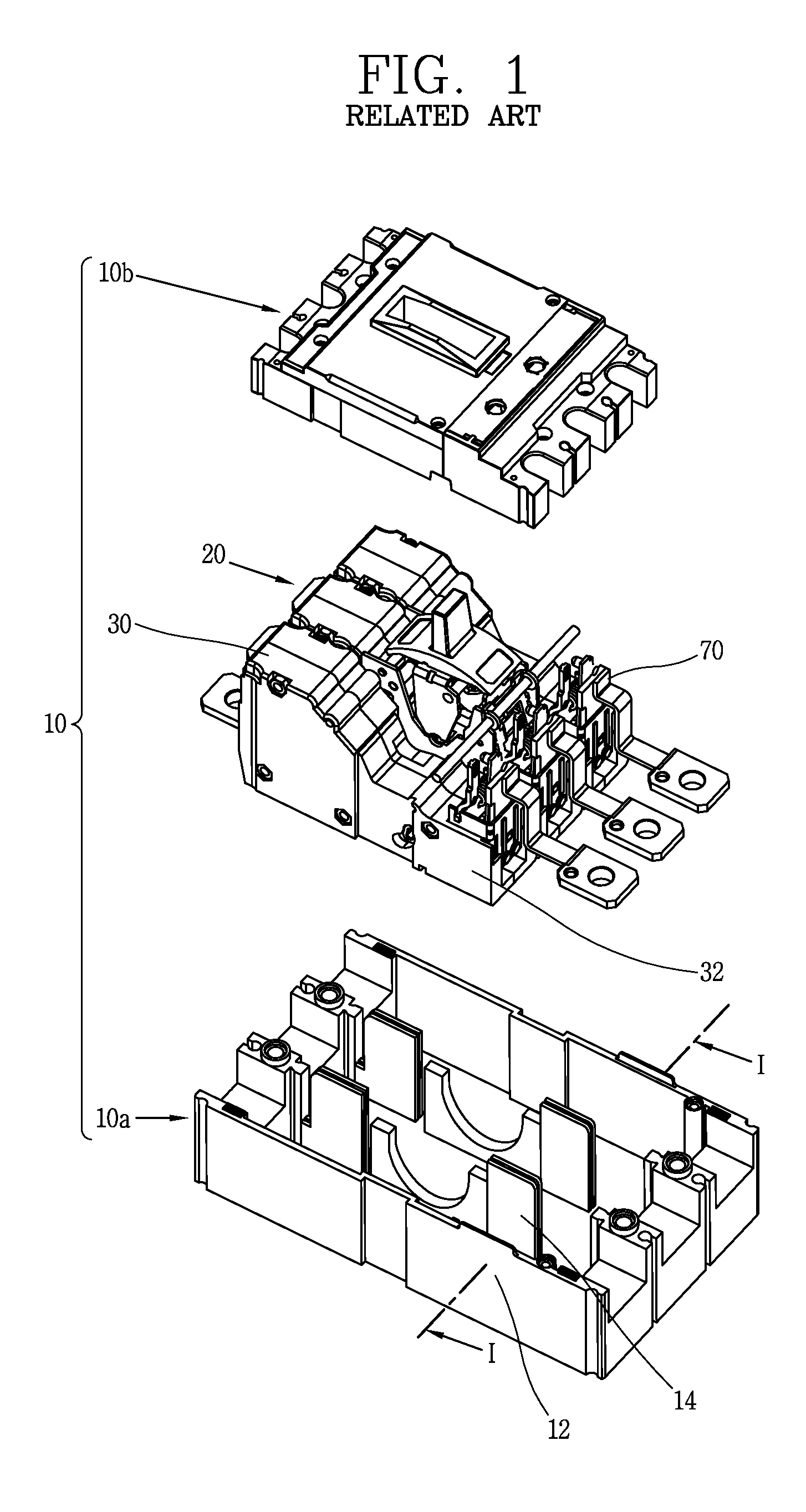
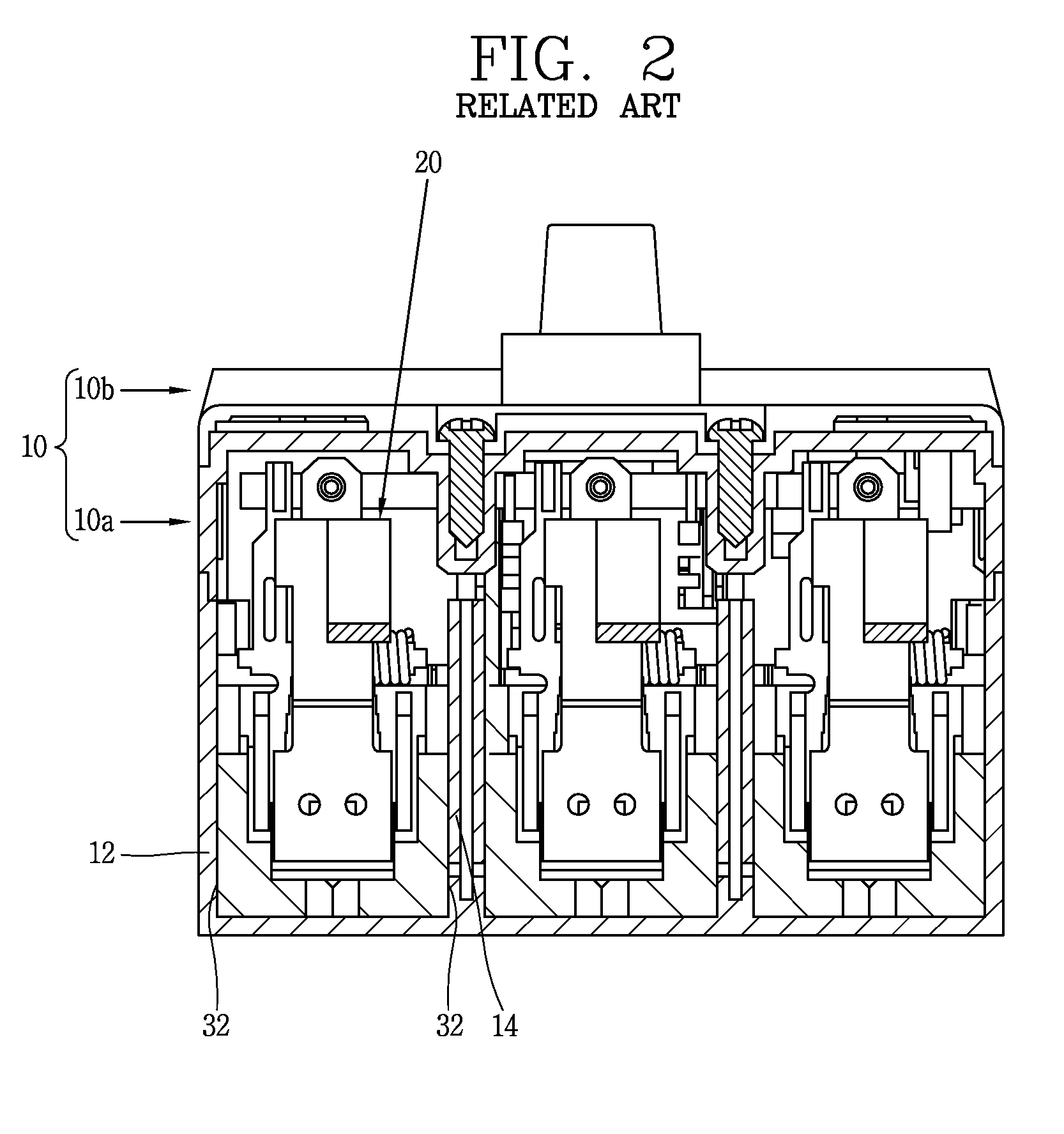
CROSS-REFERENCE TO RELATED APPLICATION[0001]Pursuant to 35 U.S.C. §119(a), this application claims the benefit of earlier filing date and right of priority to Korean Application No. 10-2014-0066318, filed on May 30, 2014, the contents of which are all hereby incorporated by reference herein in its entirety.BACKGROUND OF THE DISCLOSURE[0002]1. Field of the Disclosure[0003]This specification relates to a circuit breaker, and more particularly, a circuit breaker capable of preventing an increase in temperature.[0004]2. Background of the Disclosure[0005]As generally known, a circuit breaker is a type of an electric apparatus for protecting load devices and circuits. The circuit breaker automatically breaks a circuit when it senses that an electric circuit is manually switched on or off or a fault current, such as a short-circuit current, occurs.[0006]FIG. 1 is an exploded perspective view of the related art circuit breaker.[0007]As illustrated in FIG. 1, the related art circuit breaker ...

Claims


Application Information

Patent Timeline
Patent Type & Authority Applications(United States)
IPC IPC(8): H02H3/16H05K7/20
CPCH02H3/165H05K7/20127H05K7/20409H01H9/52H01H1/226H01H1/62H01H73/50
Inventor KIM, WOONG JAE
Owner LSIS CO LTD
Learn More