Oil-in-water drilling fluid taking biodiesel as dispersion phase as well as preparation method and application thereof

An oil-in-water drilling fluid and biodiesel technology, which is applied in chemical instruments and methods, drilling compositions, etc., can solve the problem that the drilling fluid pump and other fluid transport mechanical loads are large, and no oil-in-water drilling fluid is found in technical reports, Affecting oil-in-water drilling fluid rheology and other issues, achieving the effects of low cost, good anti-pollution performance and moderate viscosity

Active Publication Date: 2016-02-24
CHINA UNIV OF PETROLEUM (BEIJING)
View PDF10 Cites 4 Cited by
  • Summary
  • Abstract
  • Description
  • Claims
  • Application Information

AI Technical Summary

Problems solved by technology

[0008] CN1362463A discloses a high temperature resistant oil-in-water drilling fluid, the purpose of which is to solve the problem of poor high temperature resistance and high density of the drilling fluid during drilling
[0012] ①High viscosity of vegetable oil: This will affect the rheology of oil-in-water drilling fluid to a certain extent, resulting in high equivalent circulation density, easy formation leakage during drilling operations, and heavy load on fluid transport machinery such as drilling fluid pumps. Too big;
[0013] ②The cost of vegetable oil is relatively high: the cost of third to fourth grade vegetable oil is about 6,000 yuan;
[0019] After investigation, no technical report on oil-in-water drilling fluid with biodiesel as dispersed phase was found

Method used


Image

  • Oil-in-water drilling fluid taking biodiesel as dispersion phase as well as preparation method and application thereof
  • Oil-in-water drilling fluid taking biodiesel as dispersion phase as well as preparation method and application thereof
  • Oil-in-water drilling fluid taking biodiesel as dispersion phase as well as preparation method and application thereof

Examples


Embodiment 1

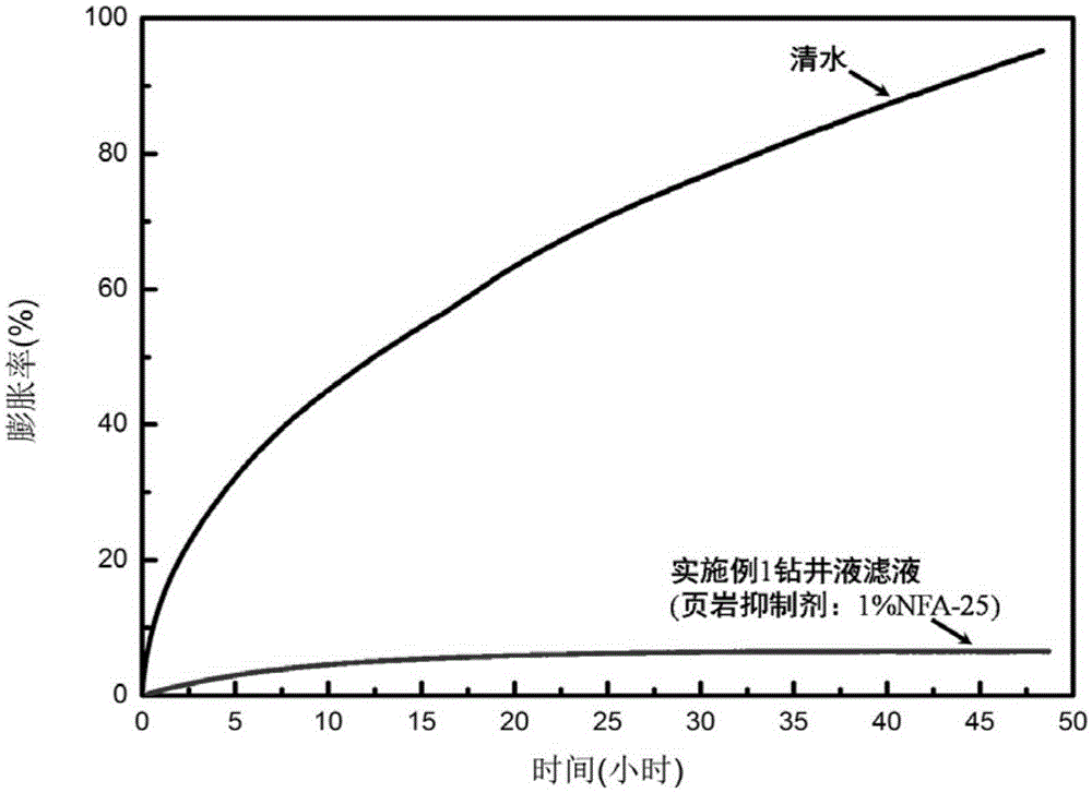
[0079] The formula of the present embodiment oil-in-water drilling fluid:

[0080] 50 parts by volume of fresh water;

[0081] 50 parts by volume of biodiesel;

[0082] And based on the total volume of fresh water and biodiesel as 100% meter: mass volume ratio (g / mL) is 0.15% sodium carbonate, mass volume ratio (g / mL) is 3% bentonite, mass volume ratio (g / mL ) is 0.03% sodium hydroxide, mass volume ratio (g / mL) is 4% main emulsifier Tween-20, mass volume ratio (g / mL) is 0.5% secondary emulsifier Span-85, mass volume ratio (g / mL) is 1% shale inhibitor NFA-25 and mass volume ratio (g / mL) is 0.6% low viscosity sodium carboxymethyl cellulose.

[0083] The preparation method of the oil-in-water drilling fluid of embodiment 1 is as follows:

[0084] Under high-speed stirring conditions, slowly add sodium carbonate, bentonite, and sodium hydroxide to fresh water in sequence, stir at high speed for 30 minutes, seal, and maintain at room temperature for 24 hours to obtain base slurr...

Embodiment 2

[0114] The formula of the present embodiment oil-in-water drilling fluid:

[0115] 70 parts by volume of fresh water;

[0116] 30 parts by volume of biodiesel;

[0117] And based on the total volume of fresh water and biodiesel as 100% meter: mass volume ratio (g / mL) is 0.2% sodium carbonate, mass volume ratio (g / mL) is 4% bentonite, mass volume ratio (g / mL ) is 0.03% sodium hydroxide, mass volume ratio (g / mL) is 3% primary emulsifier MOA-9, mass volume ratio (g / mL) is 0.5% secondary emulsifier Span-80, mass volume ratio (g / mL) is 1.2% shale inhibitor NFA-25, mass volume ratio (g / mL) is 4% fluid loss control agent (2% sulfomethyl lignite and 2% sulfomethyl phenolic resin ).

[0118] Comparing the formulas of Example 2 and Example 1, it can be seen that the main difference between the two is: in Example 2, the water-oil ratio is changed to 70:30; MOA-9 is used as the main emulsifier, and Span-80 is used as the main emulsifier. As the co-emulsifier, use a mixture of sulfomet...

Embodiment 3

[0125] The formula of the present embodiment oil-in-water drilling fluid:

[0126] 70 parts by volume of fresh water;

[0127] 30 parts by volume of biodiesel;

[0128] And based on the total volume of fresh water and biodiesel as 100% meter: mass volume ratio (g / mL) is 0.05% sodium carbonate, mass volume ratio (g / mL) is 1% bentonite, mass volume ratio (g / mL ) is 0.025% sodium hydroxide, the mass volume ratio (g / mL) is the main emulsifier MOA-9 of 2.5%, the mass volume ratio (g / mL) is the secondary emulsifier Span-80 of 0.4%, the mass volume ratio (g / mL) is 1.5% shale inhibitor NFA-25, mass volume ratio (g / mL) is 4% fluid loss control agent (2% sulfomethyl lignite and 2% sulfomethyl phenolic resin ) and a tackifier with a mass volume ratio (g / mL) of 0.1% to 0.3% (a temperature-resistant and salt-resistant polyacrylamide with a molecular weight of 16 million and a degree of hydrolysis of about 20%).

[0129] Comparing the formulas of Example 3 and Example 2, it can be seen t...


PUM

PropertyMeasurementUnit
densityaaaaaaaaaa
densityaaaaaaaaaa
densityaaaaaaaaaa

Abstract

The invention provides oil-in-water drilling fluid taking biodiesel as a dispersion phase as well as a preparation method and application thereof. The oil-in-water drilling fluid comprises 40-70 parts by volume of water and 30-60 parts by volume of biodiesel, wherein the total volume of water and biodiesel is 100%; the oil-in-water drilling fluid further comprises the following components: bentonite with the mass-to-volume ratio (g/mL) of 1%-6%, sodium carbonate with the mass-to-volume ratio of 0.05%-0.3%, sodium hydroxide with the mass-to-volume ratio of 0.02%-0.05%, a main emulsifier with the mass-to-volume ratio of 2%-5%, an auxiliary emulsifier with the mass-to-volume ratio of 0.2%-1%, a shale inhibitor with the mass-to-volume ratio of 0.5%-5% and a filtrate reducer with the mass-to-volume ratio of 0.5%-5%. The oil-in-water drilling fluid provided by the invention has the characteristics of being low in cost, non-toxic, non-fluorescent, low in density, adjustable, good in rheological property, low in filter loss, excellent in lubricating property and high in upper temperature resistance limit, and further has advantages of being excellent in antifouling property, shale inhibition property, reservoir protection property and environment acceptability.

Description

technical field [0001] The invention relates to an oil-in-water drilling fluid and its preparation method and application, in particular to an oil-in-water drilling fluid with biodiesel as a dispersed phase, its preparation method and application, and belongs to the technical field of petroleum and natural gas drilling fluids. Background technique [0002] With the rapid development of oil and gas exploration at home and abroad, the formation conditions of drilling operations are becoming increasingly complex. When drilling in low-pressure and low-permeability oil and gas reservoirs, problems such as drilling fluid loss or reservoir damage are prone to occur due to low formation pressure or developed fractures and caves. In addition, when drilling wells in some newly discovered blocks, in order to timely and accurately discover new oil and gas reservoirs and develop oil and gas resources more effectively, most of them implement underbalanced drilling operations to protect th...

Claims


Application Information

Patent Timeline
Patent Type & Authority Applications(China)
IPC IPC(8): C09K8/28
CPCC09K8/28C09K2208/12
Inventor 赵雄虎彭辉李外纪托郭君玉查潇潇
Owner CHINA UNIV OF PETROLEUM (BEIJING)
Why Eureka
Try Eureka