Optical module and optical communications device

a technology of optical communication device and optical module, which is applied in the direction of optical elements, mountings, instruments, etc., can solve the problems of increasing the output temperature reducing the output temperature-caused variation, so as to improve the characteristics of the optical module, reduce the output temperature and increase the temperature limit

Inactive Publication Date: 2009-12-08
SEIKO EPSON CORP
View PDF8 Cites 3 Cited by
  • Summary
  • Abstract
  • Description
  • Claims
  • Application Information

AI Technical Summary

Benefits of technology

[0012]An advantage of the invention is to reduce temperature-caused variation in the output of light in an optical module. It is another advantage to widen the temperature limit that allows driving of an optical module. It is still another advantage to improve the characteristics of an optical module.
[0013]An optical module according to a first aspect of the invention includes: a light source; a variable transmissivity member that is disposed on a light path of light emitted from the light source with some spacing from the light source, the variable transmissivity member being improved in transmissivity as temperature rises; and an optical fiber that receives light that has been transmitted through the variable transmissivity member.
[0014]The structure allows reduction of an impact from temperature-caused variation in the light emitted.
[0015]In the optical module, for example, a wavelength of the emitted light may increase as temperature rises. The increasing the wavelength of the emitted light, thus accompanying rise of temperature, can be used to reduce variation in the quantity of the emitted light that has been transmitted through the variable transmissivity member.
[0016]In the optical module, for example, the light source may be a vertical cavity surface emitting laser (VCSEL). Even if such laser is used, the laser having significant temperature-caused variation in the quantity of light emitted, the structure allows reduction of an impact from the temperature-caused variation.
[0017]In the optical module, for example, transmissivity of the variable transmissivity member may vary according to variation in the wavelength of incident light. The structure allows reduction of variation in the quantity of light emitted because the emitted light, in which the wavelength varies with rise of the temperature, is transmitted through the variable transmissivity member.

Problems solved by technology

However, if the driving current of the above described light emitting element is feedback controlled based on the attenuated light, the driving current will become even larger at a high temperature.
As a result, the driving current may transcend its limit value (the upper limit), becoming unable to operate, because of a shortage of output, at a temperature of a certain degree or higher.

Method used


Image

  • Optical module and optical communications device
  • Optical module and optical communications device
  • Optical module and optical communications device

Examples


first embodiment

[0041]Referring to FIGS. 1 through 6, a first embodiment of the invention will now be described.

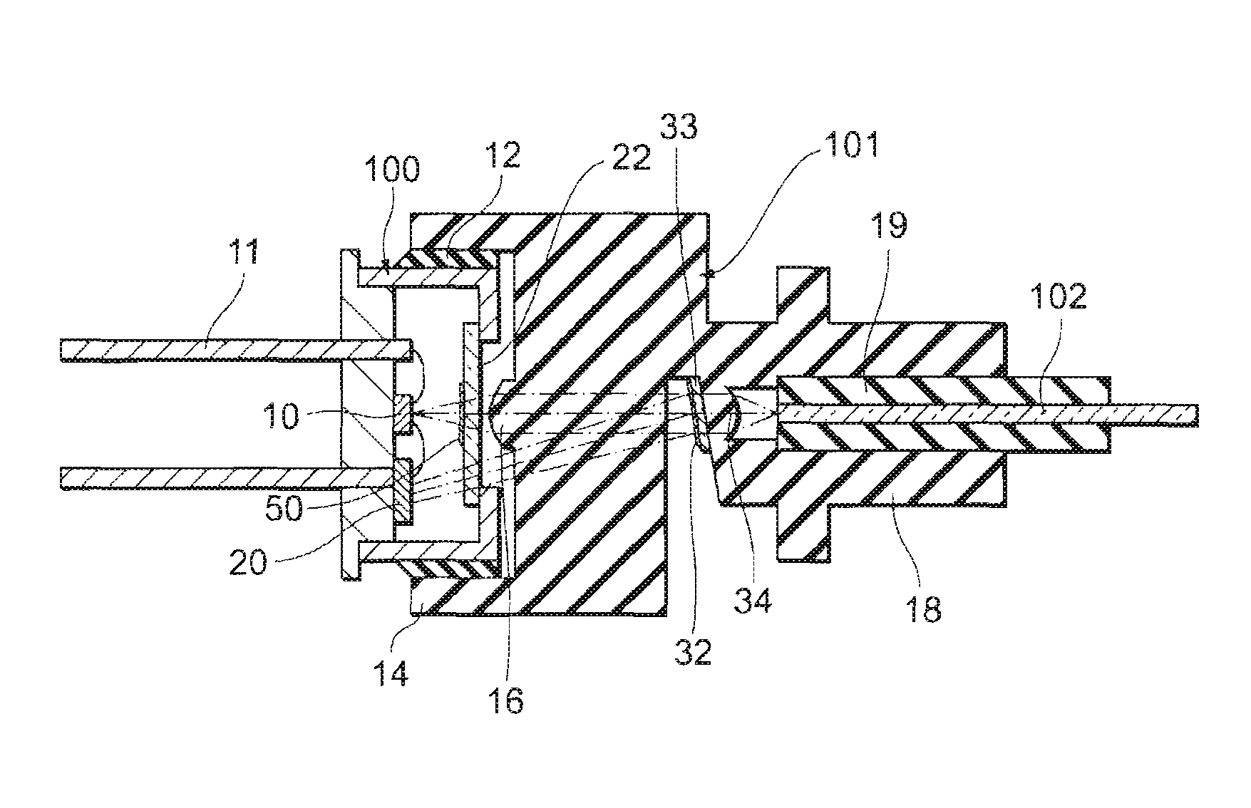
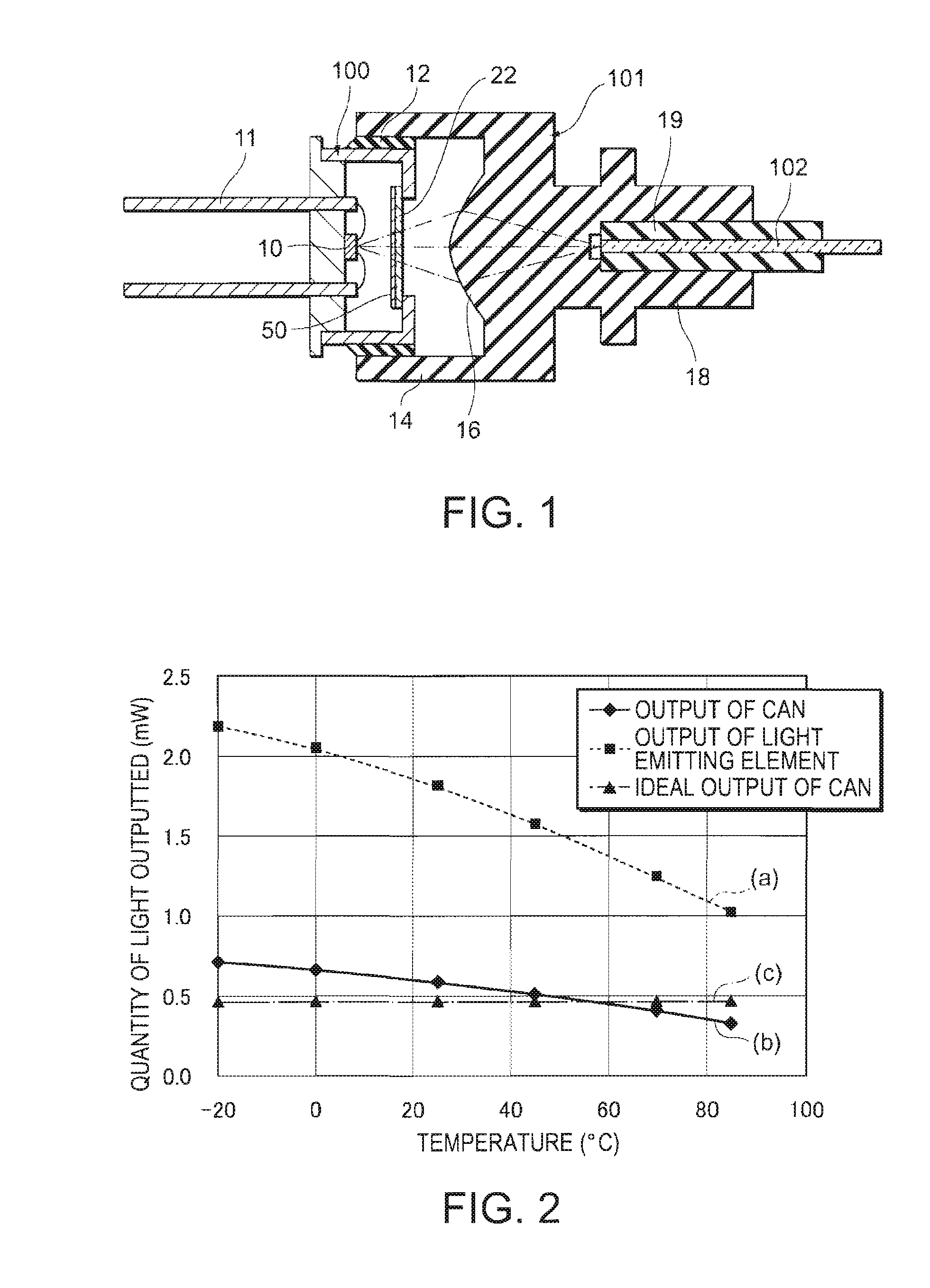
[0042]FIG. 1 is a sectional view showing the structure of an optical module (an optical transmission module, an optical transmission device, a light emitting module or an optical transmitter) according to the present embodiment. The optical module includes a CAN package (CAN) 100 and a connector 101 that are set in mutually adjusted positions and fixed by means of an adhesive 12. The connector 101 supports one end of an optical fiber 102 and optically couples the optical fiber 102 to a light emitting element (light source) 10 inside the CAN 100.

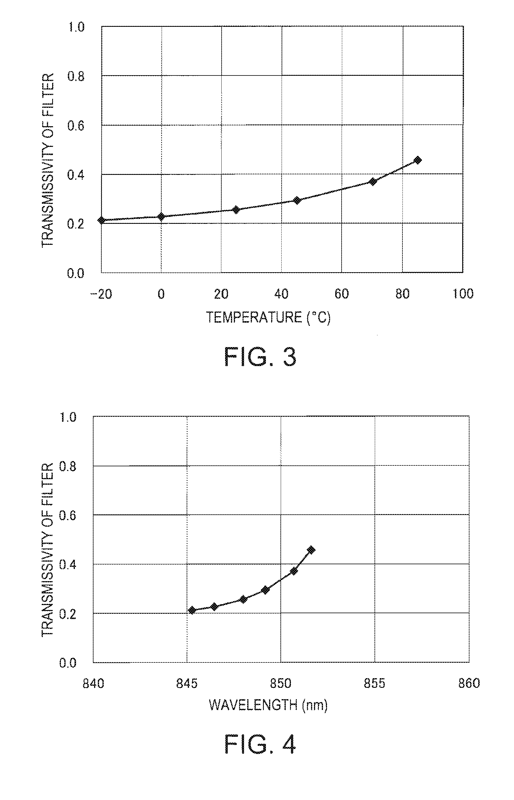
[0043]The CAN 100 includes a light emitting element 10 that is packaged in all enclosure made of a material such as a metal. In the present embodiment, a vertical cavity surface emitting laser diode (VCSEL), emitting light in multiple modes, is employed as the light emitting element 10. The wavelength of light outputted from the light emitting elem...

second embodiment

[0057]Referring to FIG. 6, a second embodiment of the invention will now be described. In the present embodiment, a monitoring light receiving element (a light quantity monitor) 20 is provided to feedback control (APC) the driving current in the light emitting element 10.

[0058]FIG. 6 is a sectional view showing the structure of an optical module according to the present embodiment. The optical module includes the CAN 100 and the connector 101, in the same way as in the first embodiment.

[0059]In the present embodiment, the CAN 100 includes a monitoring light receiving element 20 to provide a structure to monitor the output of light from the light emitting element 10. The monitoring light receiving element 20 is coupled to the lead wire 11 and furthers by way of a wire, to the light emitting element 10.

[0060]Furthermore, the connector 101 includes a partial reflection film (branching member partial reflection member) 32 and a lens (a second lens) 34. These parts are disposed on the li...

third embodiment

[0070]Referring to FIGS. 7 through 9, a third embodiment of the invention will now be described.

[0071]In contrast to the second embodiment, the wavelength filter 50 is formed over the entire surface of the glass plate 22 in the present embodiment, as shown in FIG. 7. This facilitates the process to form the wavelength filter 50. Specifically, masking and etching are rendered unnecessary here. Furthermore, it is no more required to mutually adjust the positions of the light emitting element 10 and the wavelength filter 50. On the other hand, the present embodiment does not require any other modification to be made to the contents of the second embodiment than the modification of the above described region in which the wavelength filter 60 is to be formed.

[0072]Here, however, the monitoring light receiving element 20 receives light that has twice been transmitted through the wavelength filter 50, as shown in FIG. 7.

[0073]Thus, in the present embodiment, the wavelength characteristic h...


PUM

PropertyMeasurementUnit
wavelengthaaaaaaaaaa
clad diameteraaaaaaaaaa

Abstract

An optical module includes: a light source; a variable transmissivity member that is disposed on a light path of light emitted from the light source with a spacing from the light source, the variable transmissivity member having transmissivity that increases as temperature rises; and an optical fiber that receives light that has been transmitted through the variable transmissivity member.

Description

[0001]The entire disclosure of Japanese Patent Application No. 2006-339783, filed Dec. 18, 2006 is expressly incorporated by reference herein.BACKGROUND[0002]1. Technical Field[0003]The present invention relates to an optical module and an optical communications device used for optical communication.[0004]2. Related Art[0005]There are optical modules of various forms. One known example is an optical module of a structure in which a monitoring light receiving element receives part of light emitted from a light emitting element to monitor the quantity of the light. In this case, the quantity of the light emitted sometimes varies with the ambient temperature. Thus, related art technology has aimed at minimizing the temperature characteristic of each member, such as a monitoring light receiving element or a lens, in order that a proportionality relation may be maintained between a monitored quantity of light and a fiber coupled quantity of light, regardless of the ambient temperature.[0...

Claims


Application Information

Patent Timeline
Patent Type & Authority Patents(United States)
IPC IPC(8): G02B6/36G02F1/295
CPCG02B7/008G02B6/4206G02B6/266
Inventor MIYAMAE, AKIRA
Owner SEIKO EPSON CORP
Why Eureka
Try Eureka