Optical module and optical communications device
a technology of optical communication device and optical module, which is applied in the direction of optical elements, mountings, instruments, etc., can solve the problems of increasing the output temperature reducing the output temperature-caused variation, so as to improve the characteristics of the optical module, reduce the output temperature and increase the temperature limit
- Summary
- Abstract
- Description
- Claims
- Application Information
AI Technical Summary
Benefits of technology
Problems solved by technology
Method used
Image
Examples
first embodiment
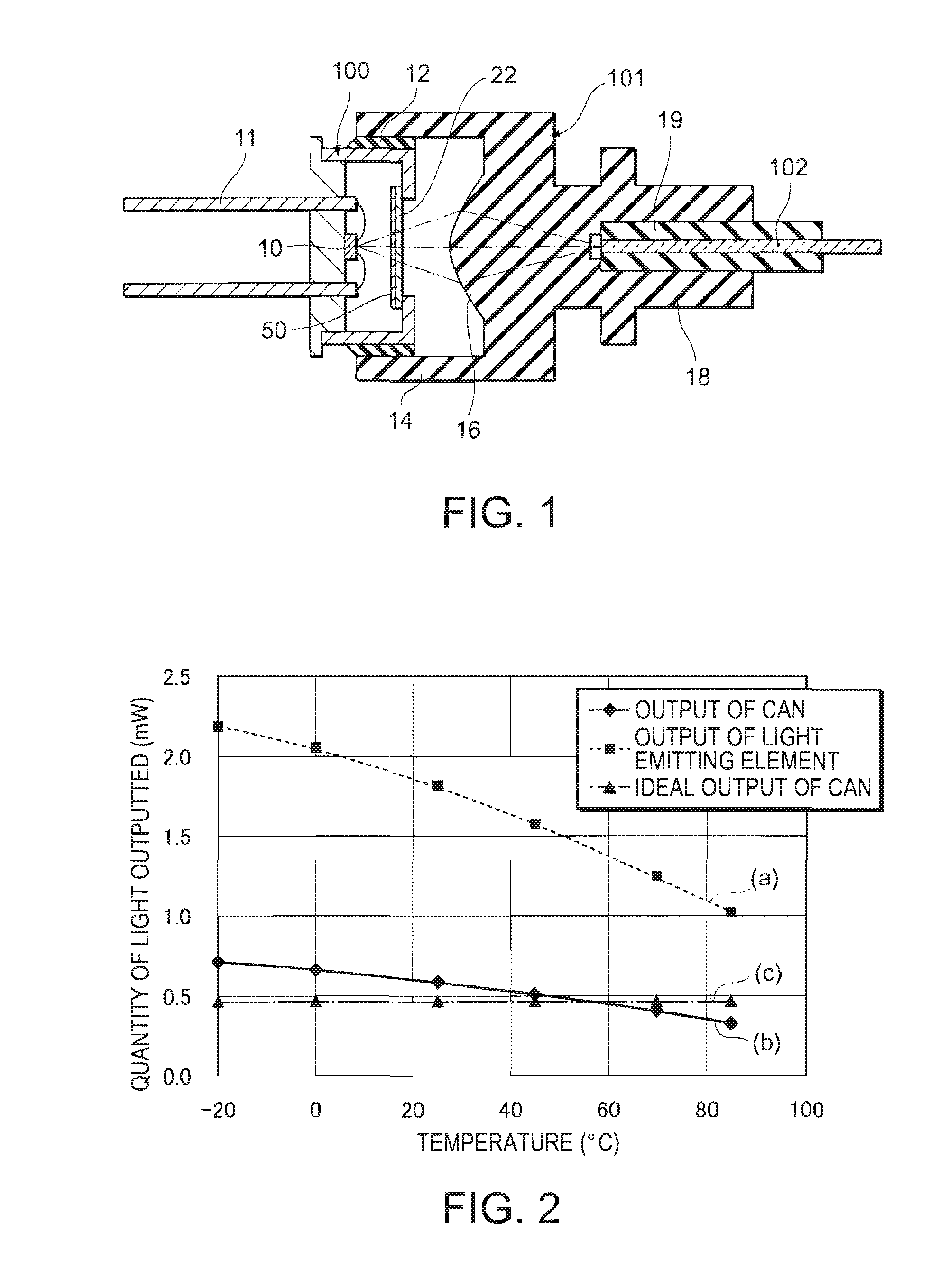
[0041]Referring to FIGS. 1 through 6, a first embodiment of the invention will now be described.
[0042]FIG. 1 is a sectional view showing the structure of an optical module (an optical transmission module, an optical transmission device, a light emitting module or an optical transmitter) according to the present embodiment. The optical module includes a CAN package (CAN) 100 and a connector 101 that are set in mutually adjusted positions and fixed by means of an adhesive 12. The connector 101 supports one end of an optical fiber 102 and optically couples the optical fiber 102 to a light emitting element (light source) 10 inside the CAN 100.
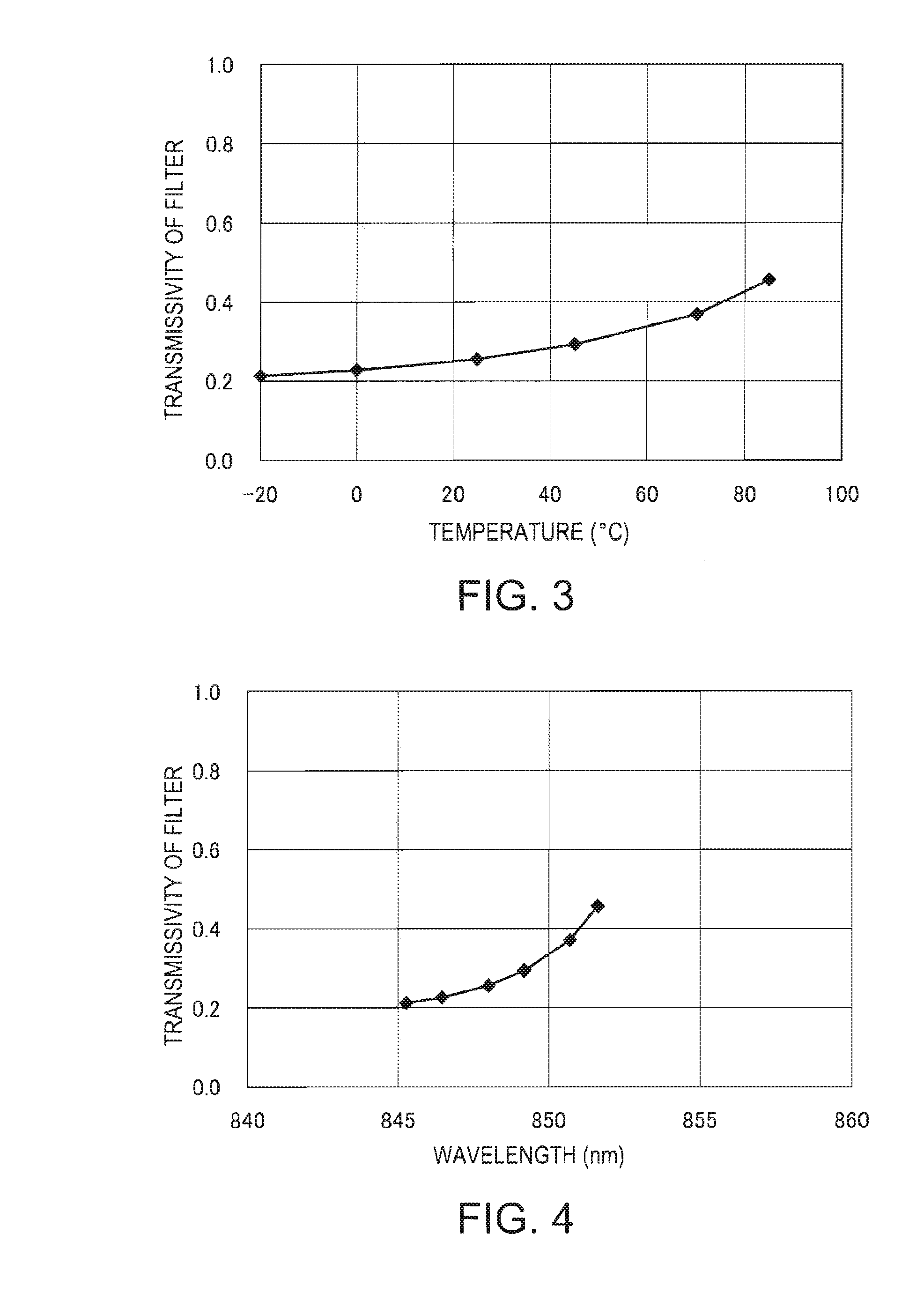
[0043]The CAN 100 includes a light emitting element 10 that is packaged in all enclosure made of a material such as a metal. In the present embodiment, a vertical cavity surface emitting laser diode (VCSEL), emitting light in multiple modes, is employed as the light emitting element 10. The wavelength of light outputted from the light emitting elem...
second embodiment
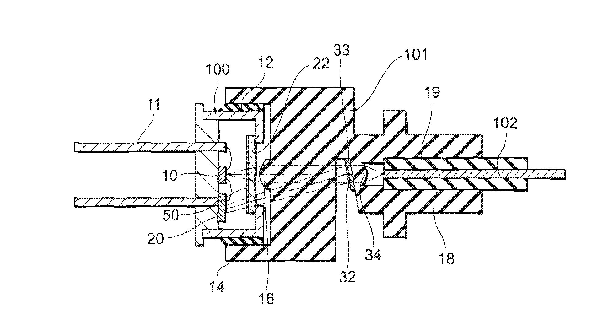
[0057]Referring to FIG. 6, a second embodiment of the invention will now be described. In the present embodiment, a monitoring light receiving element (a light quantity monitor) 20 is provided to feedback control (APC) the driving current in the light emitting element 10.
[0058]FIG. 6 is a sectional view showing the structure of an optical module according to the present embodiment. The optical module includes the CAN 100 and the connector 101, in the same way as in the first embodiment.
[0059]In the present embodiment, the CAN 100 includes a monitoring light receiving element 20 to provide a structure to monitor the output of light from the light emitting element 10. The monitoring light receiving element 20 is coupled to the lead wire 11 and furthers by way of a wire, to the light emitting element 10.
[0060]Furthermore, the connector 101 includes a partial reflection film (branching member partial reflection member) 32 and a lens (a second lens) 34. These parts are disposed on the li...
third embodiment
[0070]Referring to FIGS. 7 through 9, a third embodiment of the invention will now be described.
[0071]In contrast to the second embodiment, the wavelength filter 50 is formed over the entire surface of the glass plate 22 in the present embodiment, as shown in FIG. 7. This facilitates the process to form the wavelength filter 50. Specifically, masking and etching are rendered unnecessary here. Furthermore, it is no more required to mutually adjust the positions of the light emitting element 10 and the wavelength filter 50. On the other hand, the present embodiment does not require any other modification to be made to the contents of the second embodiment than the modification of the above described region in which the wavelength filter 60 is to be formed.
[0072]Here, however, the monitoring light receiving element 20 receives light that has twice been transmitted through the wavelength filter 50, as shown in FIG. 7.
[0073]Thus, in the present embodiment, the wavelength characteristic h...
PUM
 Abstract
Description
Claims
Application Information
 - R&D
- Intellectual Property
- Life Sciences
- Materials
- Tech Scout
- Unparalleled Data Quality
- Higher Quality Content
- 60% Fewer Hallucinations
Browse by: Latest US Patents, China's latest patents, Technical Efficacy Thesaurus, Application Domain, Technology Topic, Popular Technical Reports.
© 2025 PatSnap. All rights reserved.Legal|Privacy policy|Modern Slavery Act Transparency Statement|Sitemap|About US| Contact US: help@patsnap.com


