Smartphone or tablet mounting device and method

a technology for mounting devices and smart phones, applied in the direction of rod connections, casings/cabinets/drawers, electric devices, etc., can solve the problem of complex conventional mounting systems

Inactive Publication Date: 2015-12-10
DALTON MICHAEL T
View PDF22 Cites 17 Cited by
  • Summary
  • Abstract
  • Description
  • Claims
  • Application Information

AI Technical Summary

Benefits of technology

[0004]The present invention is a mounting apparatus for reversibly attaching a portable electronic device to a support surface, wherein the mounting apparatus comprises a support shaft, a connector device, a mounting attachment, and a mounting bracket. The support shaft may be telescoping. The connector device is secured to a first end of the support shaft for reversibly attaching the mounting apparatus to the support surface. The mounting attachment is secured to a second end of the support shaft, wherein the mounting attachment comprises a ball joint and a first locking device. The mounting bracket is secured to the mounting attachment for reversibly attaching the portable electronic device, wherein the mounting bracket comprises a second locking device. The first locking device and the second locking device are operable to reversibly fasten to each other with the ball joint therebetween so that the mounting bracket is rotatably secured to the mounting attachment. The connector device preferably comprises a magnet and the support surface preferably comprises a magnetically interactive material such that the magnet is operable to reversibly attach to the magnetically interactive support surface. In alternate embodiments, the connector device comprises a first coupling mechanism and the support surface comprises a mating second coupling mechanism such that the first coupling mechanism is operable to reversibly attach to the second coupling mechanism.

Problems solved by technology

Conventional mounting systems are complex and typically require permanent mounting to a surface.

Method used


Image

  • Smartphone or tablet mounting device and method
  • Smartphone or tablet mounting device and method
  • Smartphone or tablet mounting device and method

Examples


Embodiment Construction

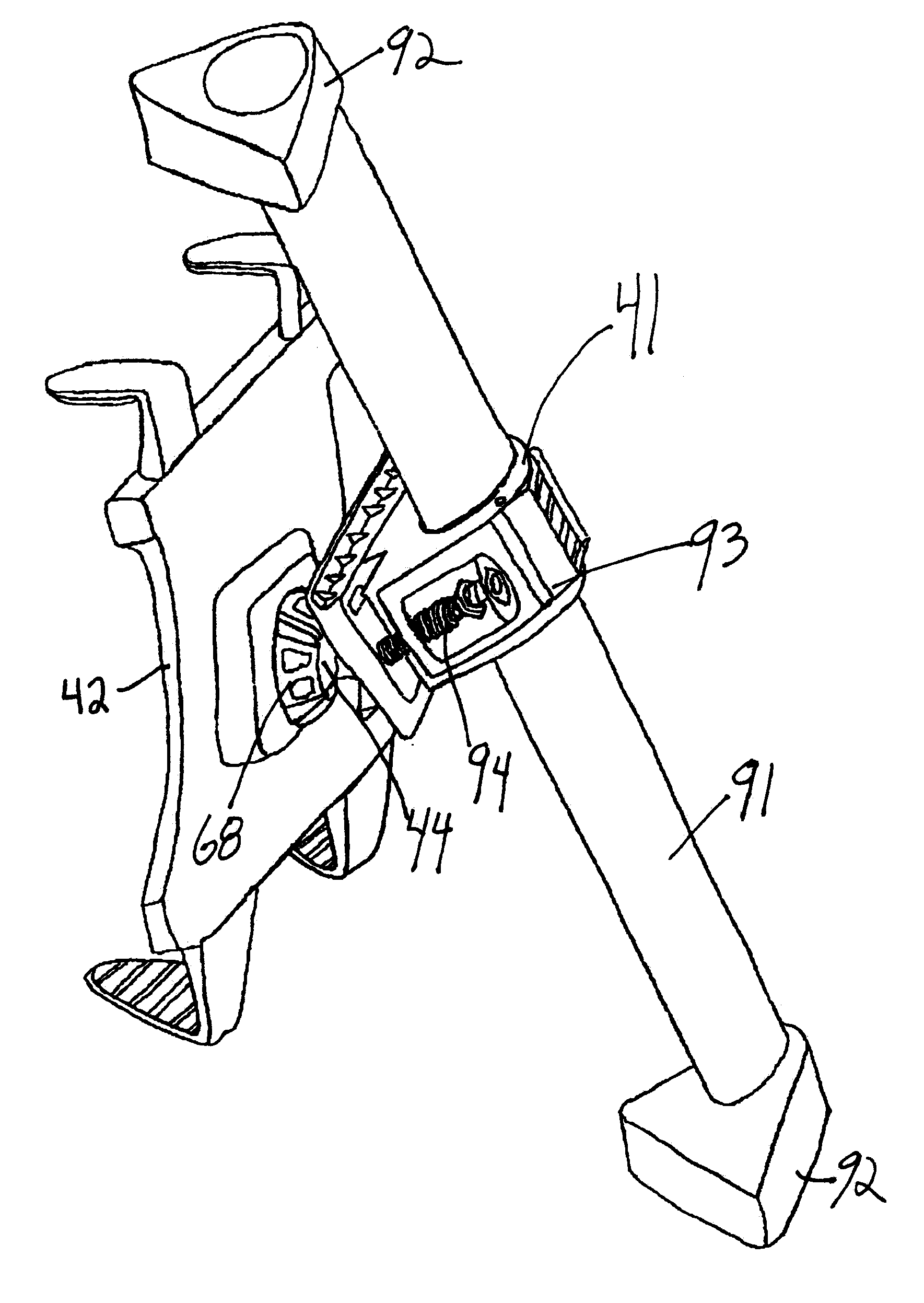
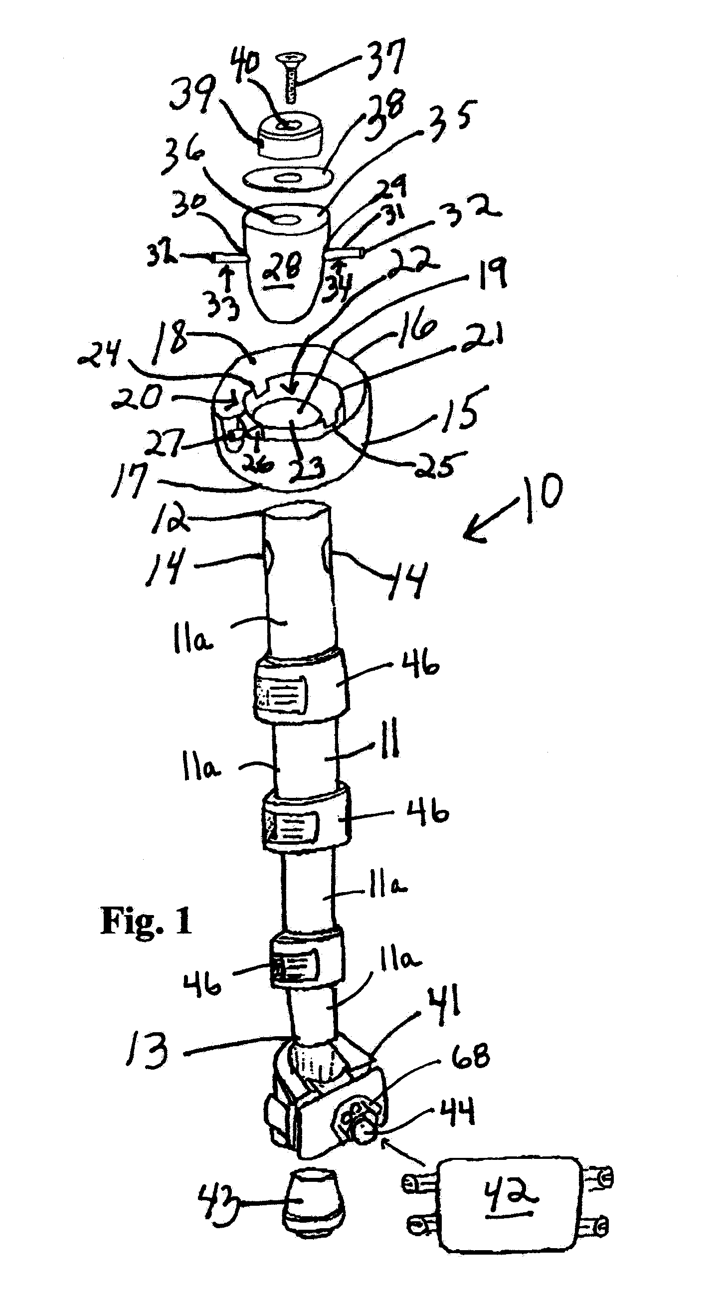
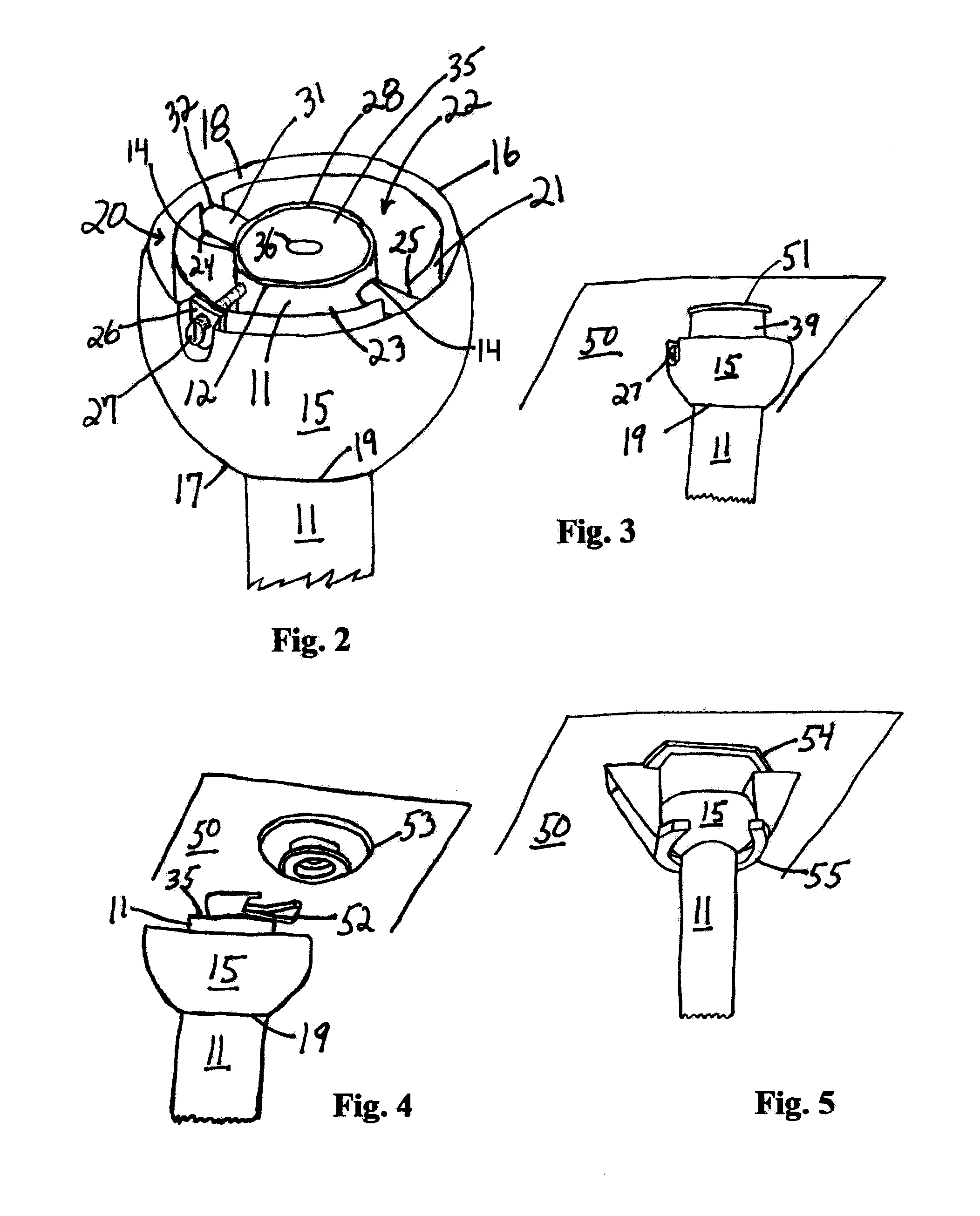
[0020]The preferred embodiments of the present invention are shown in FIGS. 1-14, wherein FIG. 1 shows an exploded view of the quick-release mount 10 of the present invention. Mount 10 has a support shaft (monopod) 11 which may be of fixed length or variable length. Shaft 11 is shown in FIG. 1 with a plurality of telescoping sections 11a securable to each other with a plurality of thumb tab locks 46. The length is adjustable, preferably, from 21 inches to 67 inches. The shaft 11 has a first end 12 and a second opposite end 13, and has holes 14 on opposite sides of shaft 11 near first end 12. A hanger ball 15 can be positioned slidably onto shaft 11 and placed below holes 14. Hanger ball 15 has a top end 16, a bottom end 17, a top opening 18, a bottom opening 19, and an interior 20. A container 21 may be fixed within the interior 20 of hanger ball 15 and encircle bottom opening 19. Container 21 has an interior 22, a top opening 23, and a first slot 24 and a second slot 25 on opposite...


PUM


Abstract

A mounting apparatus for reversibly attaching a portable electronic device to a support surface, wherein the mounting apparatus comprises a support shaft, a connector device, a mounting attachment, and a mounting bracket. The connector device is secured to a first end of the support shaft for reversibly attaching the mounting apparatus to the support surface. The mounting attachment is secured to a second end of the support shaft, wherein the mounting attachment comprises a ball joint and a first locking device. The mounting bracket is secured to the mounting attachment for reversibly attaching the portable electronic device, wherein the mounting bracket comprises a second locking device. The first locking device and the second locking device are operable to reversibly fasten to each other with the ball joint therebetween so that the mounting bracket is rotatably secured to the mounting attachment.

Description

[0001]This is a continuation of application Ser. No. 13 / 722,579 filed Dec. 20, 2012 which claimed priority from provisional application 61 / 578,635 filed Dec. 21, 2011. Applications Ser. No. 13 / 722,579 and 61 / 578,635 are hereby incorporated by reference in their entireties.FIELD OF THE INVENTION [0002]The present invention is related to a portable mounting apparatus used to support an electronic device, and more particularly, to a mounting apparatus that can be quickly and reversibly attached to various surfaces, such as vertical and horizontal surfaces, to conveniently support an electronic device for viewing.BACKGROUND OF THE INVENTION[0003]Hand-held electronic devices such as smart phones, electronic tablets, e-book readers, and the like are well known and widely used. There have been several accessories created for hands free use of these hand-held electronic devices. It would be particularly useful to have an accessory that would allow attachment of a hand-held electronic device...

Claims


Application Information

Patent Timeline
Patent Type & Authority Applications(United States)
IPC IPC(8): A47B23/00F16B7/10F16B1/00F16M13/02H05K5/02F16C11/06
CPCA47B23/007H05K5/0204A47B23/00F16B2001/0035F16B1/00F16M13/022F16B7/10F16C11/0604F16M11/14F16M11/2078F16M11/28F16M11/40F16M13/00F16M13/027F16B2200/83
Inventor DALTON, MICHAEL T.
Owner DALTON MICHAEL T
Why Eureka
Try Eureka