Control device for vehicle and control method for vehicle

a technology for controlling devices and vehicles, applied in road transportation, analogue processes for specific applications, instruments, etc., can solve problems such as the likelihood of driver feeling discomfort for insufficient vehicle deceleration, and achieve the effect of suppressing a driver's discomfor

Inactive Publication Date: 2015-12-10
TOYOTA JIDOSHA KK
View PDF0 Cites 2 Cited by
  • Summary
  • Abstract
  • Description
  • Claims
  • Application Information

AI Technical Summary

Benefits of technology

[0014]According to the control device for a vehicle and the control method for a vehicle of the invention, when the vehicle speed is lower than the lower limit vehicle speed, the second traveling mode is prohibited and the first traveling mode is executed. Therefore, it is possible to suppress a sense of discomfort of the driver due to insufficient vehicle deceleration in a low-speed area. According to the control device for a vehicle and the control method for a vehicle, when i) the vehicle speed is equal to or higher than the lower limit vehicle speed and equal to or lower than the upper limit vehicle speed, ii) the accelerator depressing amount is greater than the first depressing amount and smaller than the second depressing amount, and iii) the accelerator depressing amount variation is zero, or the control unit determines that a traveling condition is deceleration traveling based on the accelerator depressing amount variation, the second traveling mode is executed. In this way, according to the control device for a vehicle and the control method for a vehicle, it is possible to generate vehicle deceleration of proper magnitude in the low-speed area with optimizing the area where the second traveling mode is executed, and to suppress a sense of discomfort of the driver.

Problems solved by technology

For this reason, a driver is likely to feel a sense of discomfort for insufficient vehicle deceleration when the throttle opening is greater than the fully closed state.

Method used


Image

  • Control device for vehicle and control method for vehicle
  • Control device for vehicle and control method for vehicle
  • Control device for vehicle and control method for vehicle

Examples


example

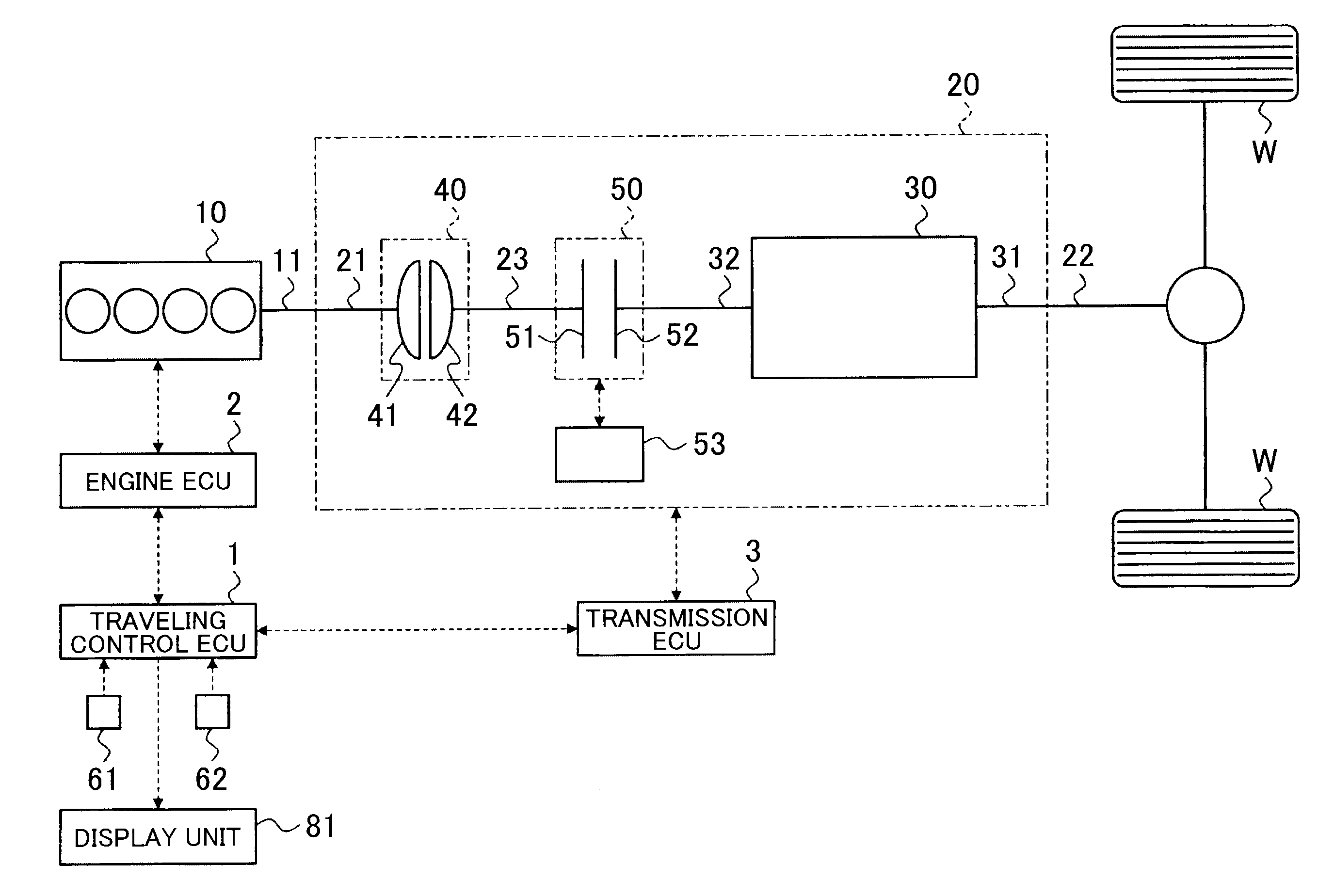
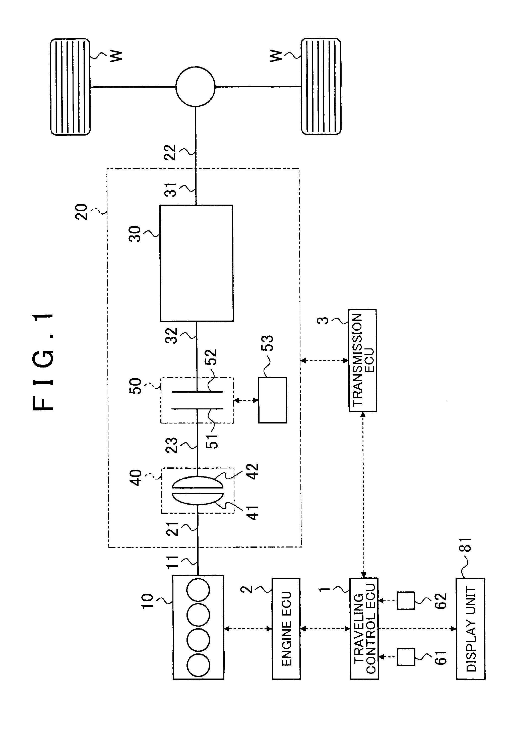
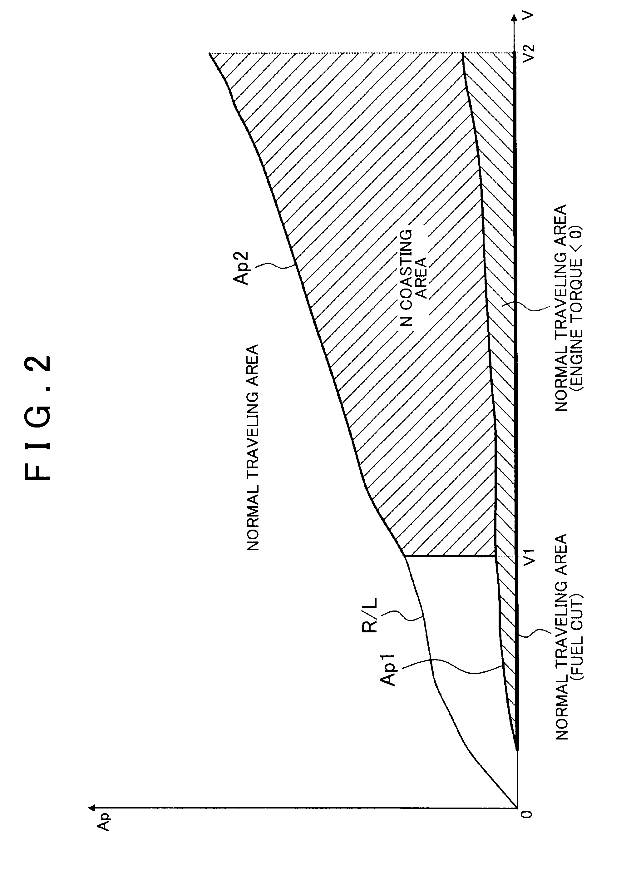
[0022]An example of a control device for a vehicle and a control method for a vehicle according to the invention will be described referring to FIGS. 1 to 5.

[0023]First, an example of a vehicle to which the control device for a vehicle and the control method for a vehicle are applied will be described.

[0024]As shown in FIG. 1, a vehicle illustrated herein is provided with an engine 10 as a power source, and an automatic transmission 20 which transmits power of the engine 10 to a driving wheel W side.

[0025]The vehicle is also provided with, as a control device for a vehicle, an electronic control device (hereinafter, referred to as “traveling control ECU”) 1 which performs control on traveling of the vehicle, an electronic control device (hereinafter, referred to as “engine ECU”) 2 which controls the engine 10, and an electronic control device (hereinafter, referred to as “transmission ECU”) 3 which controls the automatic transmission 20. The traveling control ECU 1, the engine ECU 2...


PUM


Abstract

A control device for a vehicle includes a control unit. The control unit has a first traveling mode in which a power connection and disconnection device is engaged during traveling, a second traveling mode in which the power connection and disconnection device is released during traveling, and a third traveling mode. The control unit executes the second traveling mode when i) the vehicle speed is equal to or higher than the lower limit vehicle speed and equal to or lower than an upper limit vehicle speed, ii) an accelerator depressing amount is greater than a first depressing amount and smaller than a second depressing amount, and iii) an accelerator depressing amount variation is zero, or the control unit determines that a traveling condition is deceleration traveling based on the accelerator depressing amount variation.

Description

INCORPORATION BY REFERENCE[0001]The disclosure of Japanese Patent Application No. 2014-118987 filed on Jun. 9, 2014 including the specification, drawings and abstract is incorporated herein by reference in its entirety.BACKGROUND OF THE INVENTION[0002]1. Field of the Invention[0003]The present invention relates to a control device for a vehicle and a control method for a vehicle capable of causing a vehicle to coast by cutting off power transmission between an engine and a driving wheel.[0004]2. Description of Related Art[0005]A vehicle which performs control on coasting is known. For example, Japanese Patent Application Publication No. 8-067174 (JP 8-067174 A) discloses a technique in which, when a throttle opening is greater than a fully closed state, a start clutch between an engine and a transmission is released and eco-run driving for placing the engine in an idling state is performed, when the throttle opening is greater than at the time of eco-run driving, normal driving is p...

Claims


Application Information

Patent Timeline
Patent Type & Authority Applications(United States)
IPC IPC(8): B60W30/14B60W10/02B60W10/08
CPCB60W30/143B60W10/08B60W2710/06B60W2710/021B60W10/02B60W10/04B60W30/18B60W10/06B60W30/182B60W2540/10B60W30/18072B60W2030/1809B60W2050/146B60W2520/10B60W2540/106Y02T10/40Y02T10/60B60W30/18009B60W2030/18081B60W2540/103
Inventor KATO, SHINJIYAMANAKA, SATOSHIOTSUBO, HIDEAKI
Owner TOYOTA JIDOSHA KK
Why Eureka
Try Eureka