Mass flow control for a conveyor system

a conveyor system and mass flow technology, applied in the field of mass flow metering, can solve problems such as partial or even complete obstructions that block material flow, and assume unproblematic results

Active Publication Date: 2015-12-10
RICHARD CLARENCE
View PDF6 Cites 36 Cited by
  • Summary
  • Abstract
  • Description
  • Claims
  • Application Information

AI Technical Summary

Benefits of technology

[0004]In one aspect, the present invention is directed toward a material feed system that includes a conveyor powered by a motor, a bin disposed to retain and deposit the material on the conveyor, a load transducer configured to sense total weight of the bin and retained material, a tachometer configured to produce a tachometer output reflecting conveyor speed, a motor controller configured supply the motor with a motor control command drivi

Problems solved by technology

For many applications these assumptions are unproblematic.
In asphalt processing, for example, the density of recycled asphalt shingles to be incorporated into new asphalt pro

Method used


Image

  • Mass flow control for a conveyor system
  • Mass flow control for a conveyor system
  • Mass flow control for a conveyor system

Examples


Embodiment Construction

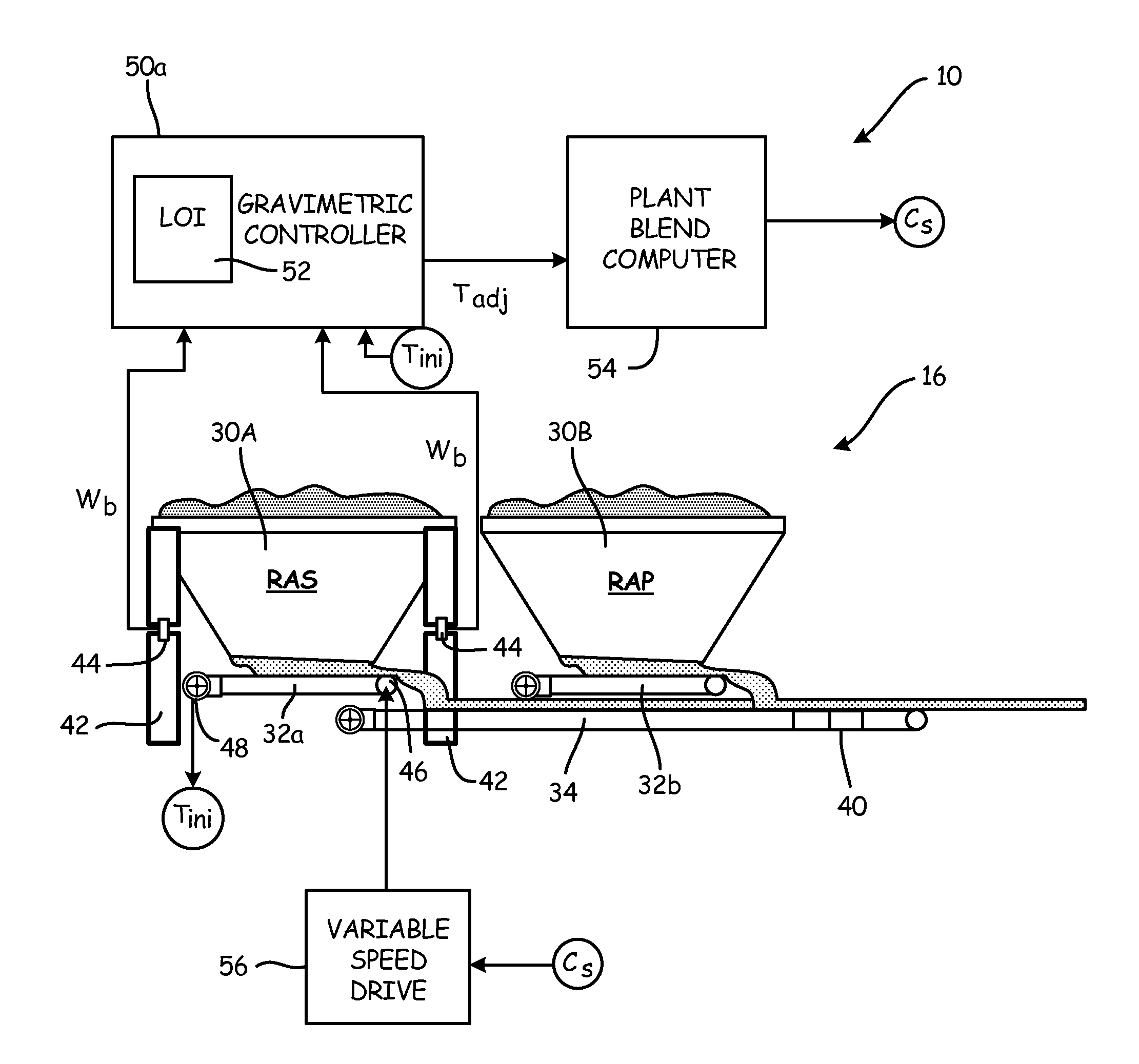
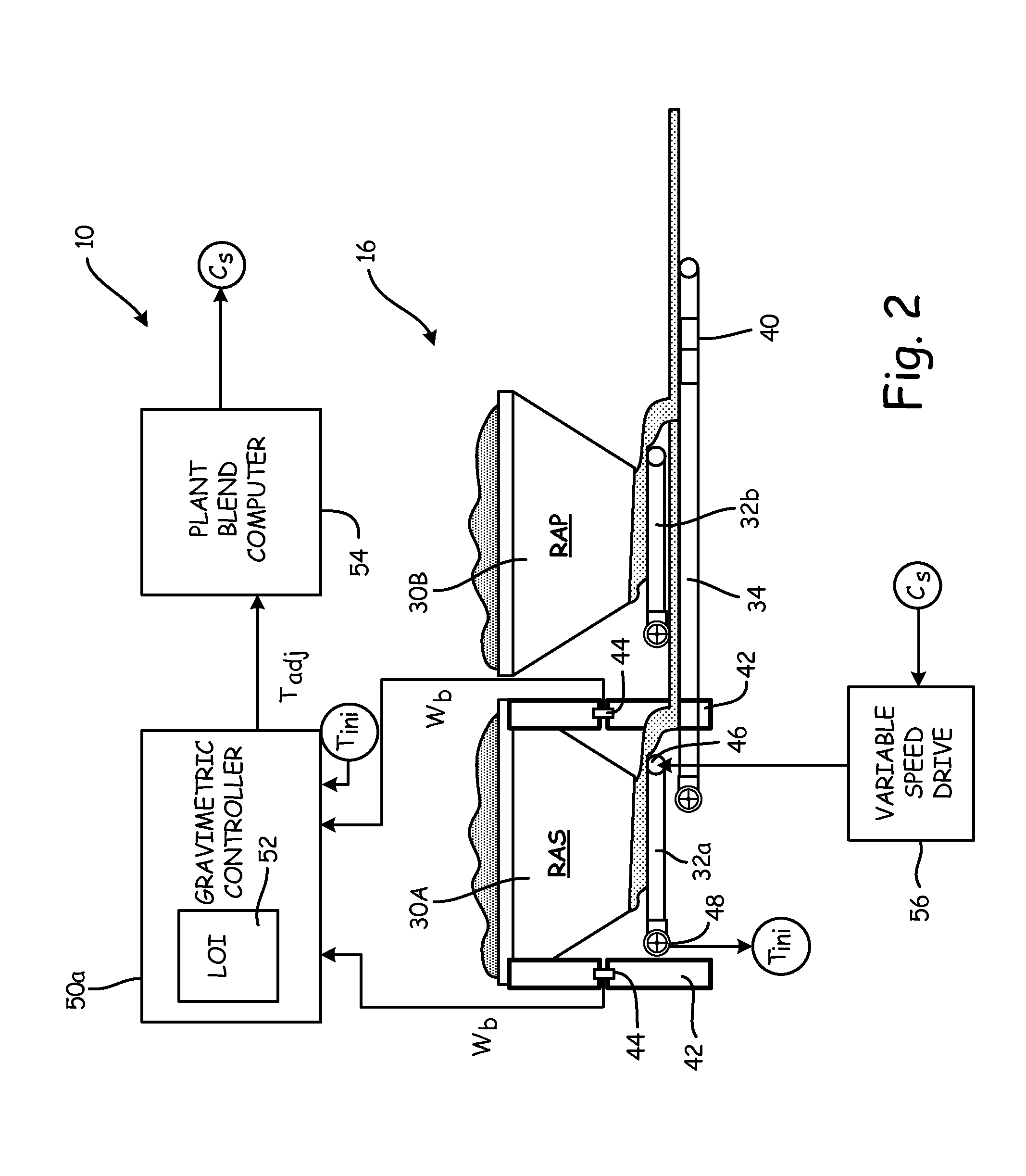
[0019]The present invention is directed toward a mass flow metering system that intercepts and adjusts control signals en route to a motor and / or volumetric mass flow controller. The mass flow metering system adjusts those control signals to account for differences between volumetric mass flow estimates and gravimetrically sensed mass flow rates, thereby improving the mass flow metering accuracy possible using existing volumetric hardware.

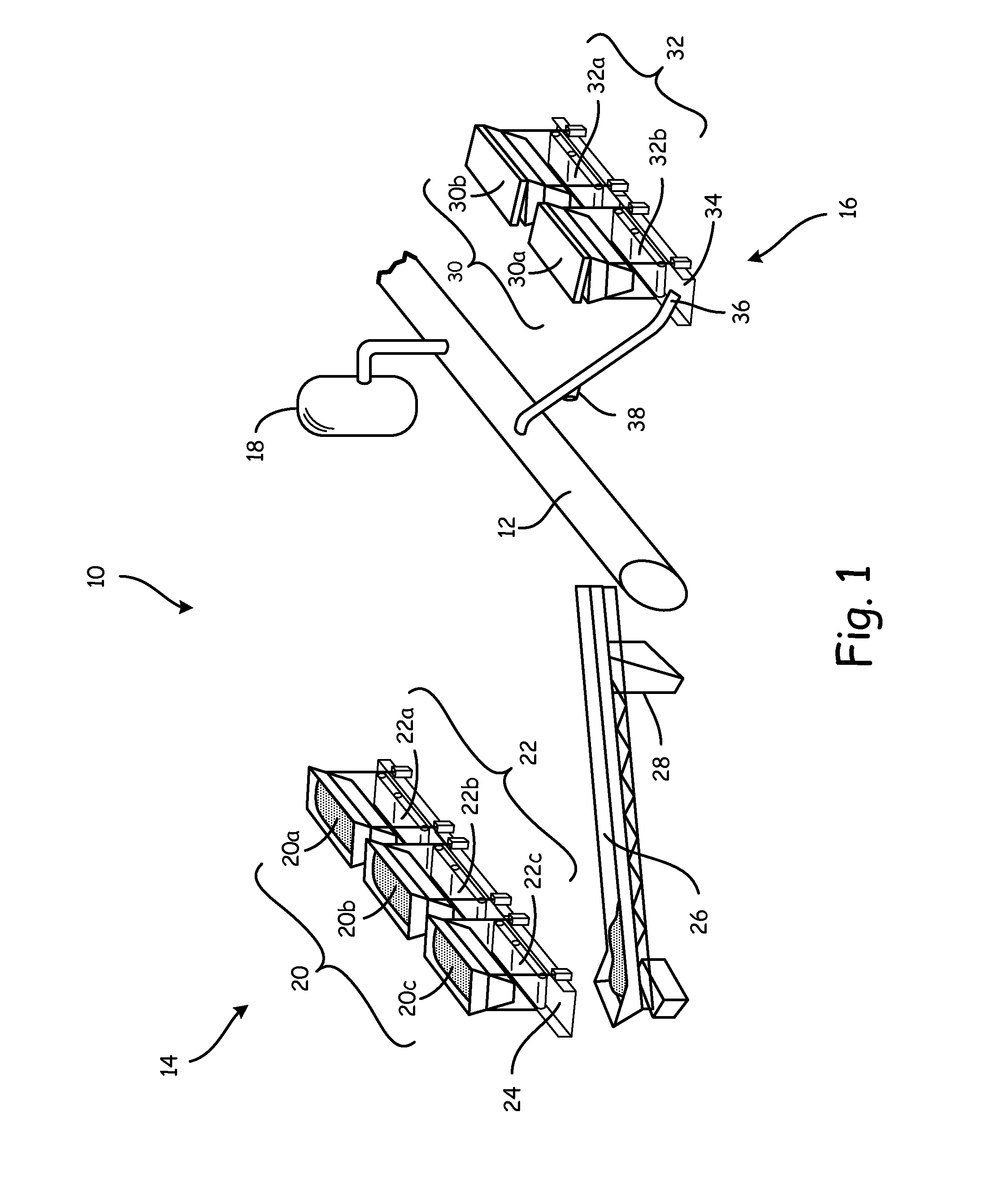
[0020]FIG. 1 is a simplified perspective view of materials processing system 10, which includes mixer 12, virgin aggregate line 14, recycled material line 16, and binder supply 18. In an illustrative embodiment, materials processing system 10 can be an asphalt processing and production plant. Virgin aggregate line 14 includes one or more aggregate bins 20 (i.e. bins 20a, 20b, and 20c) with corresponding aggregate feed conveyors 22 (i.e. conveyors 22a, 22b, and 22c) that feed main aggregate conveyor 24. Main aggregate conveyor 24 carries virgin aggr...


PUM


Abstract

A material feed system includes a conveyor powered by a motor, a bin disposed to retain and deposit the material on the conveyor, a load transducer configured to sense total weight of the bin and retained material, a tachometer configured to produce a tachometer output reflecting conveyor speed, a motor controller configured supply the motor with a motor control command driving the motor to a volumetrically estimated mass flow rate based on the tachometer, and a compensator configured to compute a gravimetric mass flow rate based on change in total weight sensed by the load transducer. The compensator is disposed to intercept and adjust either the motor control command or the tachometer output, so as to correct for differences between the volumetrically estimated mass flow rate and the gravimetric mass flow rate.

Description

CROSS-REFERENCE TO RELATED APPLICATION(S)[0001]This application claims priority of U.S. provisional application No. 62 / 008,344, filed Jun. 5, 2014, which is hereby incorporated by reference in its entirety.BACKGROUND[0002]The present invention relates generally to mass flow metering, and more particularly to a conveyor system for using gravimetric metering to control mass flow.[0003]Conveyor belts are used in a variety of applications to transport bulk solid material. Most processing systems using conveyor belts monitor or meter mass flow in some way. Such systems typically estimate mass flow volumetrically, by multiplying a monitored and controlled belt speed by a fixed estimate of linear material density (e.g. kg / m). Such estimates assume that mass flow is dependent only on belt speed, and ignore variations in belt coverage (i.e. variations in width and depth of material on the conveyor belt), material density (e.g. kg / m3), and transport speed (e.g. due to blockage of the belt). F...

Claims


Application Information

Patent Timeline
IPC IPC(8): B65G43/08G05B19/402B65G65/42
CPCB65G43/08B65G65/42G05B2219/45054B65G2811/0689B65G2811/096G05B19/402B65G47/19G05B13/025
Inventor RICHARD, CLARENCE
Owner RICHARD CLARENCE
Why Eureka
Try Eureka