
Mobile communication system and downlink transmission power control method thereof

a technology of transmission power control and mobile communication system, which is applied in the field of mobile communication system, can solve the problems of large decoding enlarge the difference of downlink transmission power between the base stations, and increase the error rate of tpc command signal decoding

Inactive Publication Date: 2006-02-23
NEC CORP
View PDF4 Cites 10 Cited by
  • Summary
  • Abstract
  • Description
  • Claims
  • Application Information

AI Technical Summary

Benefits of technology

[0018] It is therefore an object of this invention to provide a mobile communication system capable of correcting difference of transmission power between base stations concerned with soft hand-over and a downlink transmission power control method therefor.

Problems solved by technology

Consequently, in the base station, decoding error rate for the TPC command signal becomes large.
On the other hand, when the mobile terminal communicates with plural base stations, the mistaken variation becomes a problem.
In theory, there is a case where a succeeding decoding error regarding a succeeding TPC command signal in any base stations cancels the difference of the downlink transmission power between the base stations.
However, in practice, the succeeding decoding error often enlarges the difference of the downlink transmission power between the base stations concerned with the soft hand-over.
Accordingly, the mobile terminal can not receive a downlink signal from any base stations concerned with the soft hand-over with sufficient receiving power.
As mentioned above, the (former) known method has fear that forced call clearing is caused by mistaken decoding of the TPC signal at any base station when soft hand-over is executed.
However, the method does not consider about the mistaken decoding for the TPC signal during the soft hand-over.

Method used


Image

  • Mobile communication system and downlink transmission power control method thereof
  • Mobile communication system and downlink transmission power control method thereof
  • Mobile communication system and downlink transmission power control method thereof

Examples


Embodiment Construction

[0034] Referring to FIGS. 1 to 10, description will be made about a mobile communication system according to a preferred embodiment of this invention.

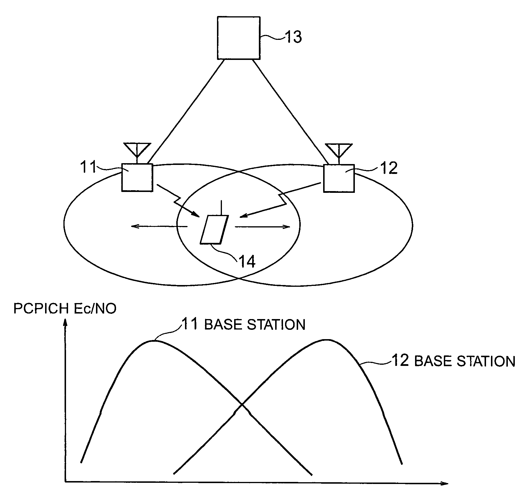
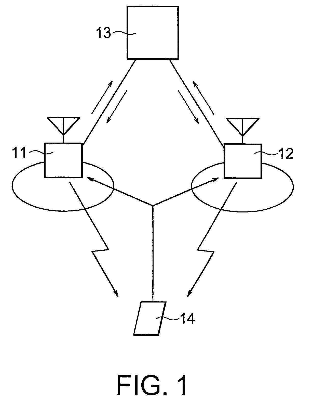
[0035]FIG. 1 is a schematic diagram of a wideband code division multiple access (W-CDMA) wireless network system as the mobile communication system. In FIG. 1, the network system includes a plurality of base stations (only two shown) 11 and 12, a wireless network controller 13 connected to the base stations 11 and 12 through asynchronous transfer mode (ATM) lines and at least one mobile terminal 14 connectable with the base stations 11 and 12 through wireless connections based on the W-CDMA wireless access system.

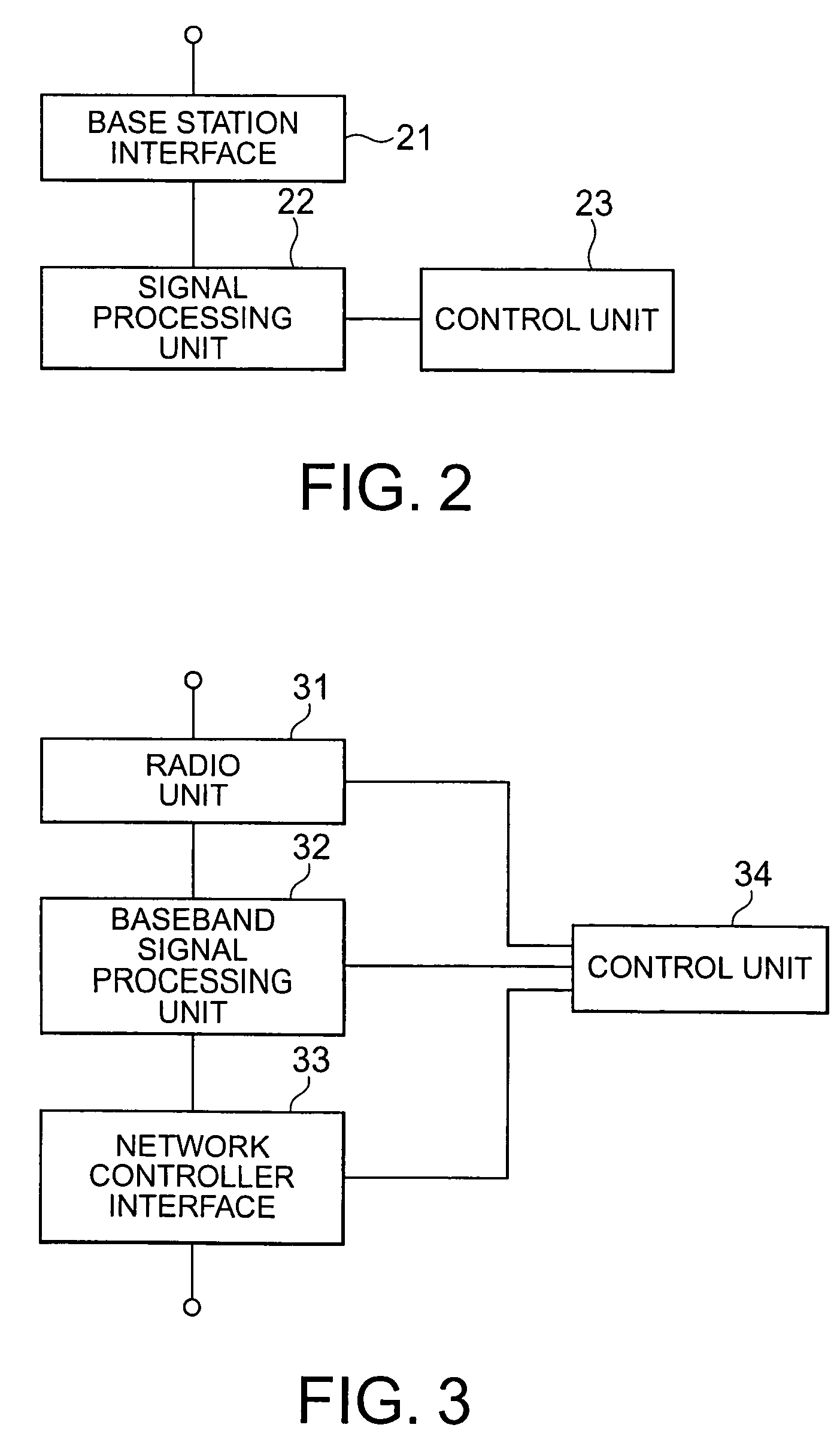
[0036] As illustrated in FIG. 2, the wireless network controller 13 has a base station interface 21 to be connected to the base stations 11 and 12, a signal processing unit 22 for processing signals from the base station 11 and 12, and a control unit 23 for controlling an operation of the whole of the wireless network contro...


PUM


Abstract

Base stations concerned with soft hand-over respecting a mobile terminal notify sums of control values to a wireless network controller at intervals of the predetermined number of frames. In each base station, the control values are obtained by decoding common transmission power control signals transmitted by the mobile terminal at intervals of time slot shorter than the frame. The mobile terminal notifies ratios of signal power to noise power regarding common pilot signals transmitted by the base stations. The wireless network controller selects one of the base stations as a reference station according to the ratios of signal power to noise power. The wireless network controller instructs the base stations to match transmission power of the base station(s) other than the reference station to that of the reference station.

Description

[0001] This application claims priority to prior application JP 2004-233457, the disclosure of which is incorporated herein by reference. BACKGROUND OF THE INVENTION [0002] This invention relates to a mobile communication system, in particular, to a downlink transmission power control method of a wideband code division multiple access (W-CDMA) mobile communication system. [0003] In a mobile communication system employing code division multiple access (CDMA), a plurality of base stations and a plurality of mobile terminals use a common frequency band. Accordingly, transmission power control is necessary to suppress interference. [0004] A known transmission power control method adopts a combination of an inner loop control, which brings a reception SIR (Signal to Interference Ratio) close to a target SIR, and an outer loop control, which updates the target SIR according to receiving quality. Such a transmission power control method is disclosed in Unexamined Japanese Patent Publicatio...

Claims


Application Information

Patent Timeline
IPC IPC(8): H04Q7/20H04J13/00H04W36/00H04W52/04H04W52/40
CPCH04W52/40H04W52/143
Inventor INNAMI, TAKAHARU
Owner NEC CORP
Learn More