
Sound field control device

Active Publication Date: 2010-11-25
YAMAHA CORP
View PDF5 Cites 11 Cited by
  • Summary
  • Abstract
  • Description
  • Claims
  • Application Information

AI Technical Summary

Benefits of technology

[0012]Therefore, it is an object of the invention to provide a sound field control device which can appropriately correct a difference in the degree of the sound field effect caused by a difference in the reproduction environment.
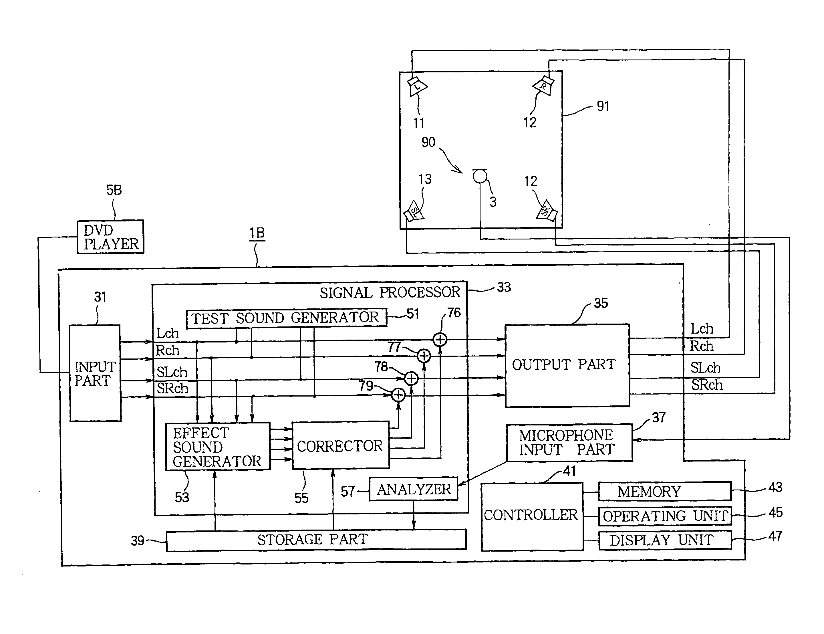
[0017]According to this configuration, the sound field control device can correct the volumes of sound field effect sounds (i.e., sounds simulating reflected sounds generated in a music hall or the like), which are generated based on the sound field effect information, based on acoustic states in the reproduction environment, i.e., based on a result of the inspection of states of reflected sounds generated through reflection of the sound from walls in the reproduction environment and then can emit the sound field effect sounds through a plurality of speakers. Accordingly, the sound field control device can allow the reproduction environment to approximate an ideal environment, regardless of the reproduction environment, by correcting the volumes of the sound field effect sounds according to the reproduction environment.
[0018]In addition, when the ratio between the first and second factors is excessively high or low, the sound field effect sounds generated based on the sound field effect information might be different from intended ones, causing a problem that the sound field effect sounds are excessively greater or smaller than the direct sound of the input signal. In the sound field control device of the invention, the correction part sets a limit to the ratio between the first factor and the second factor when correcting the volume of the sound field effect sound. Due to this configuration, it is possible to limit the volume of the sound field effect sound within a predetermined range, thereby preventing the occurrence of such a problem.
[0019]In the sound field control device of the invention, a plurality of speakers may be connected to an output part and the first and second factors of the speakers may be different. In this case, it is possible to determine and use respective representative values of the first and second factors according to the reproduction environment. In this case, the determination part determines a representative value of the first factors and a representative value of the second factors, and the correction part corrects the volume of the sound field effect sound using the representative values. Accordingly, it is possible to suppress the amount of processing for calculation, thereby reducing calculation load or calculation time.
[0021]According to the invention, the sound field control device can allow the reproduction environment to approximate an ideal reproduction environment, regardless of the reproduction environment, by appropriately correcting a difference in the degree of the sound field effect according to the reproduction environment. This allows the listener to enjoy a sense of presence or reality through the sound field effect regardless of the installation place of the sound field control device or speakers.

Problems solved by technology

The conventional sound field control device has a problem in that an intended sound field effect is not obtained due to a difference in a real reproduction environment such as a difference in the direction or the arrangement of speakers within a room.
If the sound field effect is too strong, the sound field effect interferes with listening since the sound field effect sounds harsh.
On the other hand, if the sound field effect is too weak, the practical value of the sound field effect function is reduced since it is hard to hear the sound field effect sound.

Method used


Image

  • Sound field control device
  • Sound field control device
  • Sound field control device

Examples


Embodiment Construction

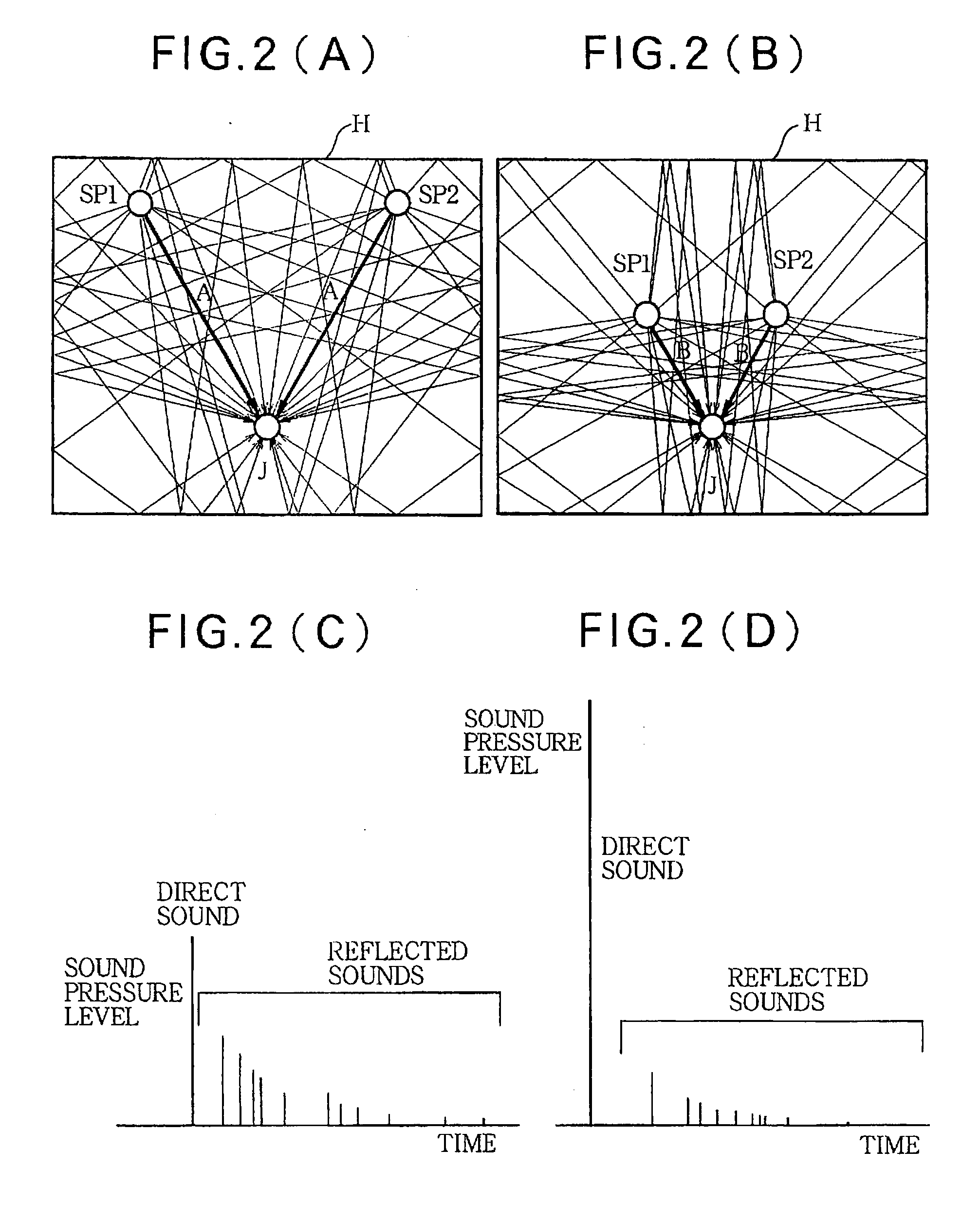
[0027]Before describing the details of the invention, first description is given as to variation in the sound field effect due to difference in the reproduction environments, for better understanding of the invention. FIGS. 2(A) to 2(F) illustrate difference in the sound field effect dependent on nature of the reproduction environments. As shown in FIG. 2(A), left and right sound sources SP1 and SP2 are installed at symmetrical positions at a distance A from a sound receiving point (listening position) J in a room H and emit sounds toward the sound receiving point J. In this case, as the sounds are emitted, a direct sound reaching directly to the sound receiving point J without reflection with walls is generated, and concurrently a plurality of reflected sounds which are reflected by walls of the room H and which arrive at the sound receiving point J are generated. A reproduction space shown in FIG. 2(A) is referred to as a “reproduction environment A”.

[0028]On the other hand, as sh...


PUM


Abstract

A sound field control device has an input part through which an audio signal is input. A storage part stores a first factor obtained by calculating a proportion of energy of direct sound in total energy of sound collected in an adjustment environment within a predetermined time. A sound field generation part generates a sound field effect sound from the audio signal input through the input part, and outputs the sound field effect sound at a volume corresponding to the first factor. A calculation part calculates a second factor which represents a ratio of an energy of a direct sound to an energy of sound which is collected in a reproduction environment and which contains the direct sound. A correction part corrects the volume of the sound field effect sound based on a ratio between the first factor and the second factor.

Description

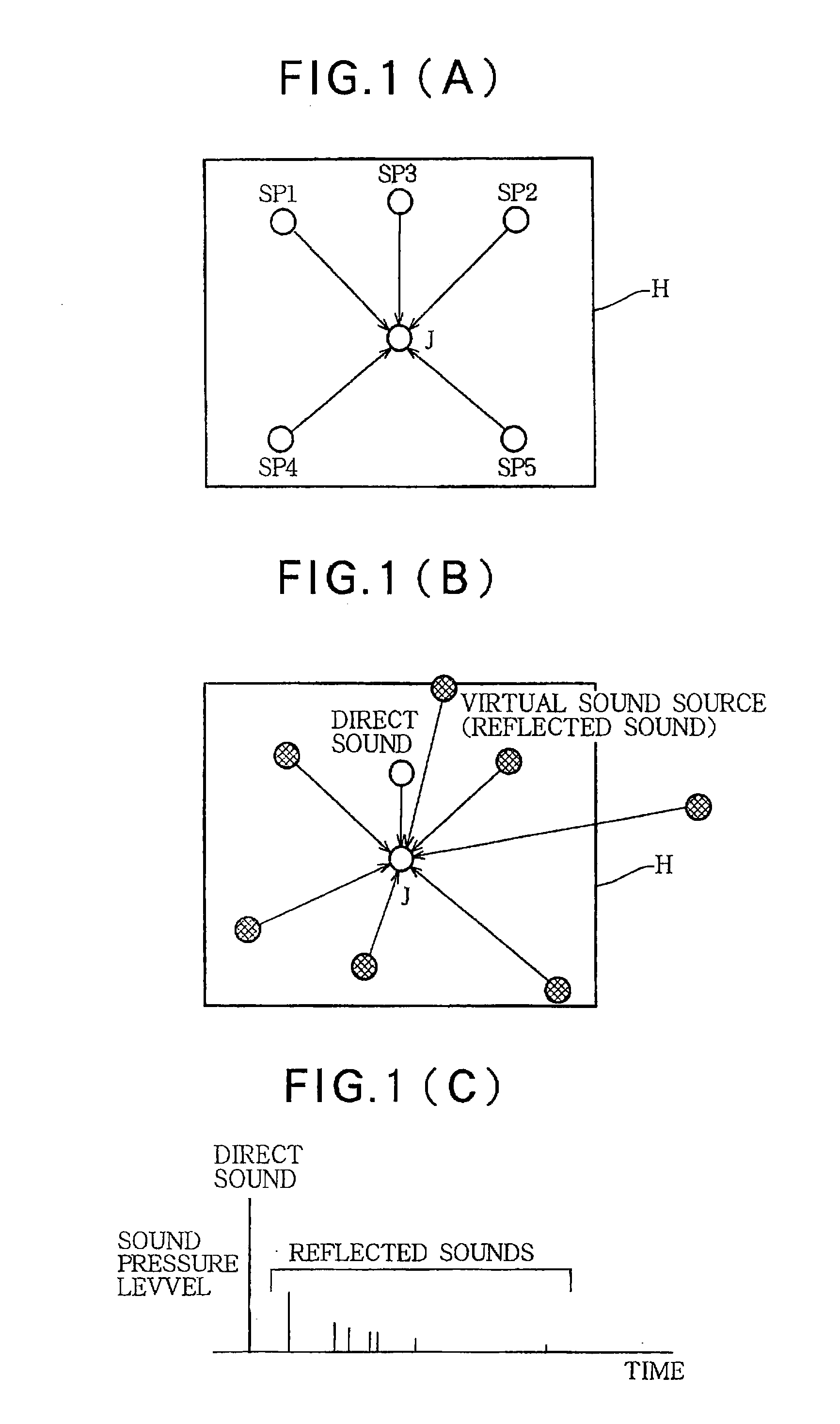
BACKGROUND OF THE INVENTION[0001]1. Technical Field of the Invention[0002]The present invention relates to a sound field control device that imparts a sound field effect to an audio signal to control a sound field, and more particularly to sound field effect control according to a reproduction environment where the audio signal is reproduced.[0003]2. Description of the Related Art[0004]A conventional sound field control device imparts a sound field effect to sound of audio contents and controls the sound field (for example, see Japanese Patent No. 2755208). The sound field effect is an effect for reproducing sounds simulating reflected sounds generated in an acoustic space such as a concert hall to allow the listener to experience a sense of presence or reality such that the listener feels as though they were located in a different space such as a real concert hall while they are actually located in a room.[0005]FIGS. 1(A) to 1(C) are conceptual diagrams illustrating a conventional ...

Claims


Application Information

Patent Timeline
IPC IPC(8): H03G3/20
CPCH04S7/305
Inventor OHASHI, NORIYUKI
Owner YAMAHA CORP
Learn More