
Air-fuel ratio imbalance among cylinders determining apparatus for an internal combustion engine

a technology of air-fuel ratio and determining apparatus, which is applied in the direction of machines/engines, electric control, instruments, etc., can solve the problems of air-fuel ratio non-uniformity among the cylinders, imbalance among the individual cylinder air-fuel ratios, and large differences in the air-fuel ratios of the cylinders

Active Publication Date: 2011-11-10
TOYOTA JIDOSHA KK
View PDF5 Cites 11 Cited by
  • Summary
  • Abstract
  • Description
  • Claims
  • Application Information

AI Technical Summary

Benefits of technology

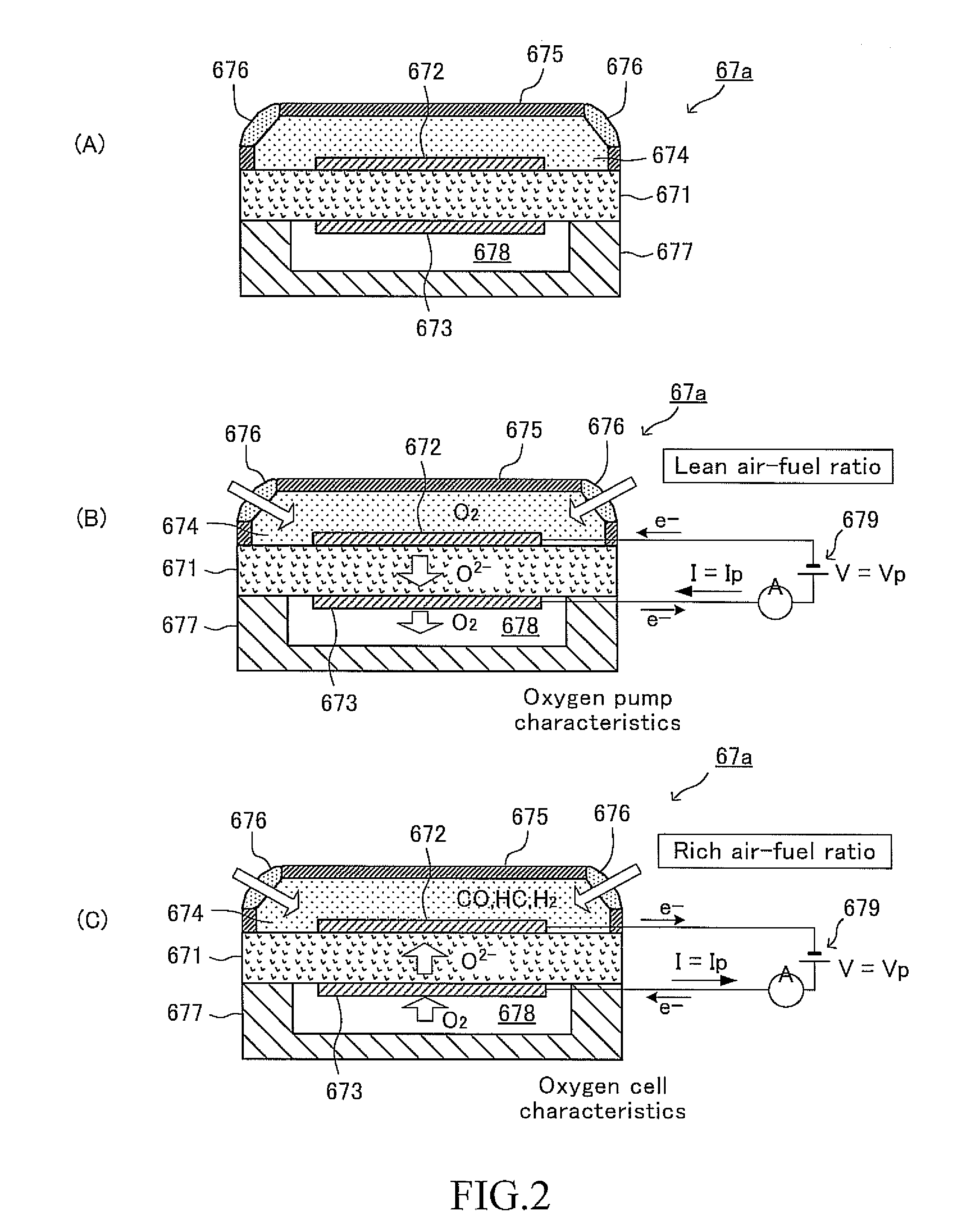
[0027]However, the present inventors have found that, when the air-fuel ratio of the exhaust gas fluctuates in an air-fuel region which is very close to the stoichiometric air-fuel ratio, the state occurs in which “the output value Vabyfs of the air-fuel ratio sensor does not vary with respect to (or in response to) the fluctuation in the air-fuel ratio of the exhaust gas with having high responsivity (the state in which the responsivity of the air-fuel ratio sensor becomes poor or low)”, and therefore, the parameter for imbalance determination obtained based on the air-fuel-ratio-variation-indicative-value does not indicate “a degree of the air-fuel ratio imbalance (state) among cylinders” with an adequate precision, and accordingly, a case arises in which air-fuel ratio imbalance determination can not be performed with high accuracy. It should be noted that the above mentioned “air-fuel region which is very close to the stoichiometric air-fuel ratio” is an air-fuel region having a certain range which includes the stoichiometric air-fuel ratio, and can be referred to as “the stoichiometric air-fuel ratio region”. Further, “the degree of the air-fuel ratio imbalance (state) among cylinders” means the individual cylinder air-fuel-ratio difference, that is, the difference between the imbalance cylinder air-fuel ratio and the normal cylinder air-fuel ratio.
[0082]The second order differential value (d2(Vabyfs) / dt2, or d2(abyfs) / dt2) with respect to time of the output value of the air-fuel ratio sensor or the detected air-fuel ratio which is the air-fuel ratio represented by the output value of the air-fuel ratio sensor is hardly affected by a graduate (slow) change in an average value of the air-fuel ratio of the exhaust gas. Accordingly, it is possible to obtain the parameter for imbalance determination as “a value accurately representing the difference between individual cylinder air-fuel-ratios” even when the average value of the air-fuel ratio of the exhaust gas varies relatively gradually, by obtaining, as the basic indicative value, these second order differential values, and by obtaining the parameter for imbalance determination based on the obtained basic indicative value.

Problems solved by technology

That is, an imbalance among air-fuel ratios of the cylinders (a variation in air-fuel ratios among the cylinders, air-fuel ratio non-uniformity among the cylinders) becomes large.
In other words, there arises an imbalance among “the individual-cylinder-air-fuel-ratios”, each of which is an air-fuel ratio of a mixture supplied to each of the cylinders.
However, the air-fuel ratio of the specific cylinder is still richer (smaller) than the stoichiometric air-fuel ratio, and the air-fuel ratios of the other cylinders are still leaner (larger) than the stoichiometric air-fuel ratio, and therefore, a combustion condition of the mixture in each of the cylinders is different from a perfect combustion.
Accordingly, although the average of the air-fuel ratios of the mixtures supplied to the engine coincides with the stoichiometric air-fuel ratio, the three-way catalytic converter can not purify the increased emission, and thus, there is a possibility that the emission becomes worse.
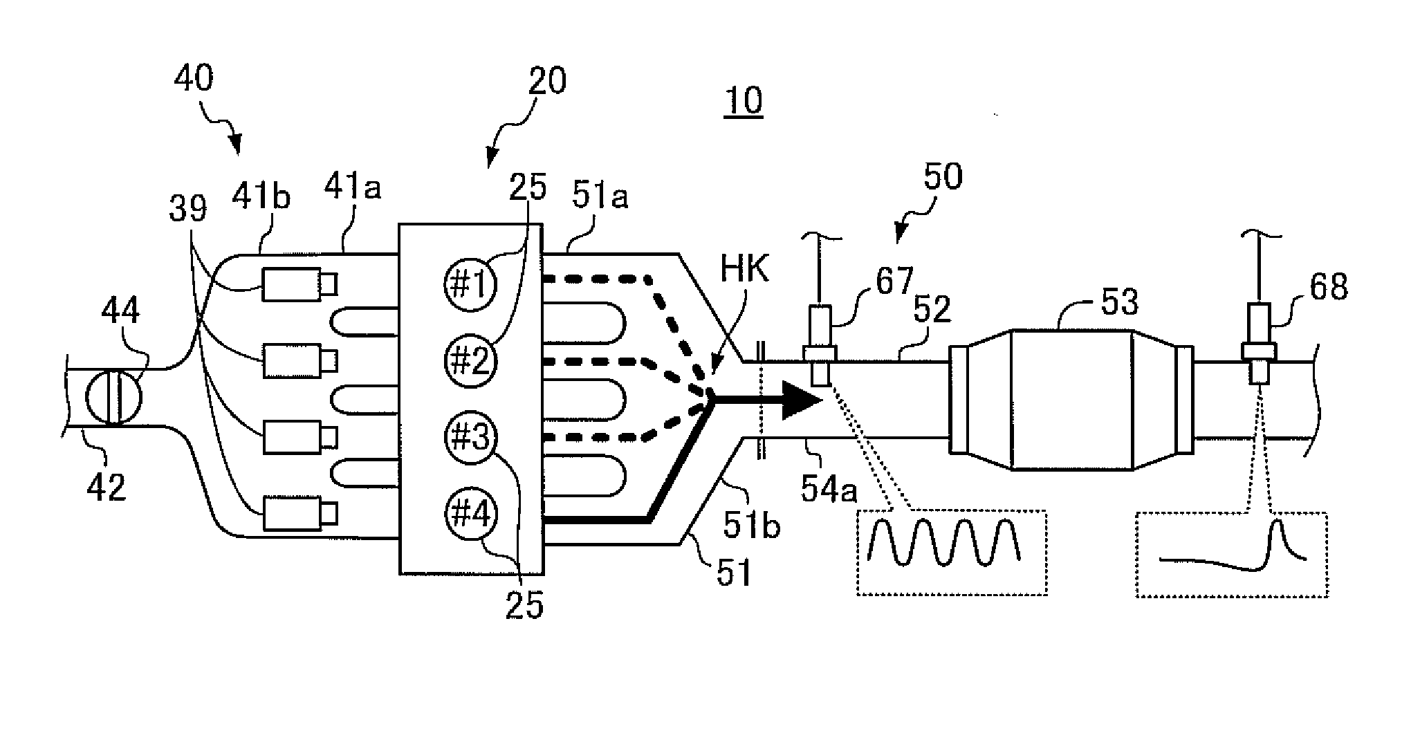
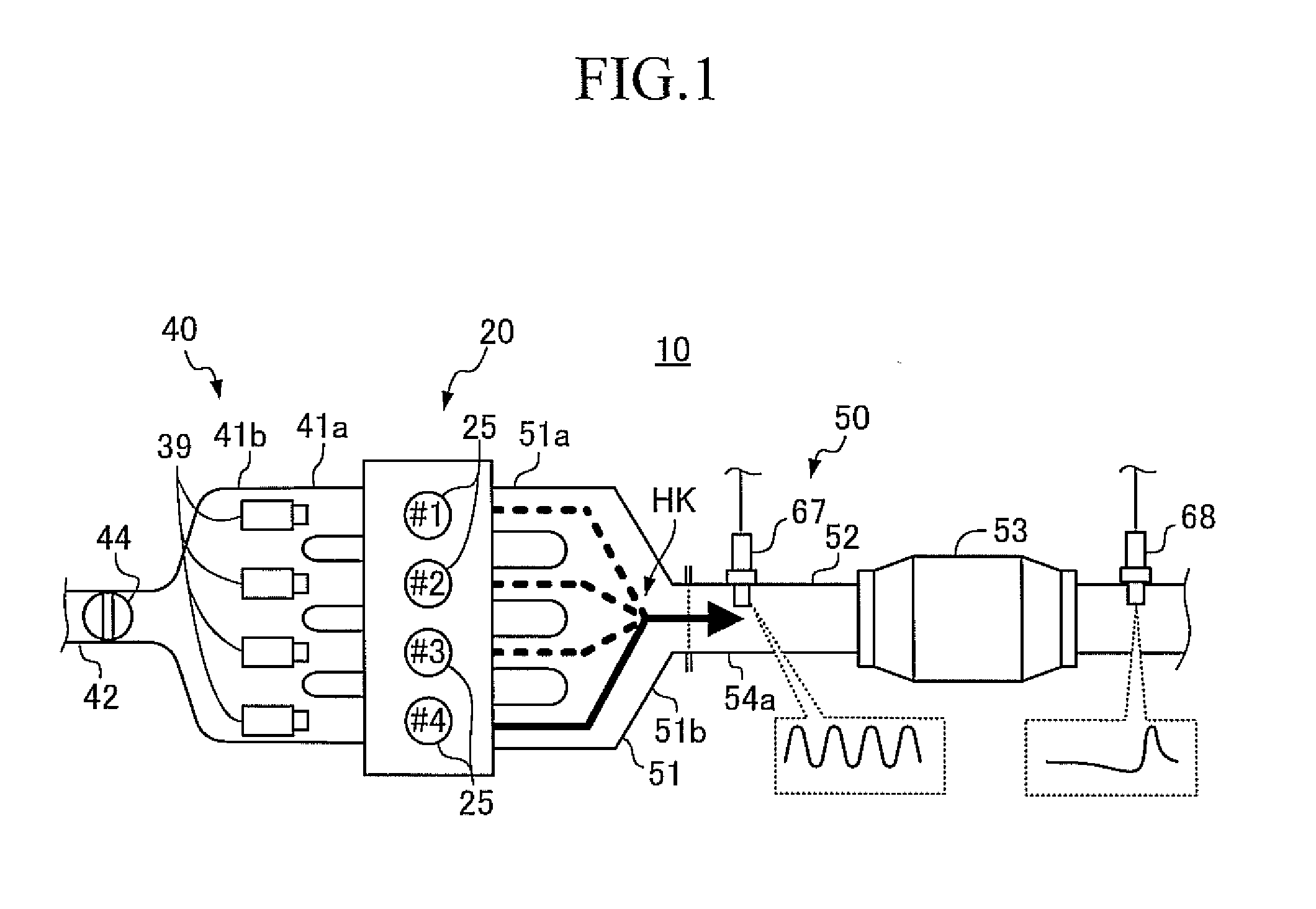
It should be noted that the air-fuel ratio imbalance among cylinders occurs when a characteristic of an injector of a specific cylinder becomes “a characteristic that the injector injects fuel by an amount which is excessively smaller than the instructed fuel injection amount”.

Method used


Image

  • Air-fuel ratio imbalance among cylinders determining apparatus for an internal combustion engine
  • Air-fuel ratio imbalance among cylinders determining apparatus for an internal combustion engine
  • Air-fuel ratio imbalance among cylinders determining apparatus for an internal combustion engine

Examples


first embodiment

Structure

[0101]FIG. 7 schematically shows the configuration of a system configured such that a determining apparatus according to a first embodiment (hereinafter also referred to as the “first determining apparatus”) is applied to a 4 cycle, spark-ignition, multi-cylinder (e.g., in line 4 cylinder) internal combustion engine 10. It should be noted that FIG. 7 shows a sectional view of a specific cylinder, however, the other cylinders have similar configurations.

[0102]This internal combustion engine 10 includes a cylinder block section 20 including a cylinder block, a cylinder block lower-case, an oil pan, etc.; a cylinder head section 30 fixed on the cylinder block section 20; an intake system 40 for supplying gasoline gas mixture to the cylinder block section 20; and an exhaust system 50 for discharging exhaust gas from the cylinder block section 20 to the exterior of the engine.

[0103]The cylinder block section 20 includes cylinders 21, pistons 22, connecting rods 23, and a cranksh...

second embodiment

[0234]Next will be described a determining apparatus (hereinafter simply referred to as “a second determining apparatus”) according to a second embodiment of the present invention.

[0235]The second determining apparatus firstly sets the target air-fuel ratio abyfr to (at) the stoichiometric air-fuel ratio stoich. More specifically, the second determining apparatus sets the target air-fuel ratio abyfr to (at) the stoichiometric air-fuel ratio stoich when the condition for obtaining a parameter for imbalance determination is not satisfied, except for a particular case such as an after-engine-start-condition.

[0236]The second determining apparatus obtains the parameter X for imbalance determination (the air-fuel-ratio-variation-indicative-value AFD) while the apparatus maintains the target air-fuel ratio abyfr at the stoichiometric air-fuel ratio stoich, when the condition for obtaining a parameter for imbalance determination is satisfied, according to a manner similar to a manner of the...

third embodiment

[0276]Next will be described a determining apparatus (hereinafter simply referred to as “a third determining apparatus”) according to a third embodiment of the present invention.

[0277]The third determining apparatus obtains the tentative parameter and the final parameter, similarly to the second determining apparatus. Hereinafter, in order to clearly differentiate between the tentative parameter and the final parameter, the tentative parameter X is expressed as Xz and the final parameter is expressed as Xs.

[0278]The third determining apparatus obtains a difference ΔX between the tentative parameter Xz and the final parameter Xs, and determines that the air-fuel ratio imbalance (state) among cylinders is occurring when an absolute value |ΔX| of the difference ΔX is larger than the threshold value ΔXth. To the contrary, the third determining apparatus determines that the air-fuel ratio imbalance (state) among cylinders is not occurring when the absolute value |ΔX| of the difference ΔX...


PUM

PropertyMeasurementUnit
angleaaaaaaaaaa
angleaaaaaaaaaa
crank angleaaaaaaaaaa

Abstract

An air-fuel ratio imbalance among cylinders determining apparatus (a determining apparatus) according to an aspect of the present invention, obtains a parameter X for imbalance determination which becomes larger as a variation of an air-fuel ratio of an exhaust gas passing through a position at which the air-fuel ratio sensor is disposed becomes larger, based on an output value Vabyfs of an air-fuel ratio sensor 67. At the same time, the determining apparatus changes a target air-fuel ratio which is a target value of an air-fuel ratio of a mixture supplied to an engine to “an air-fuel ratio (a target rich air-fuel ratio AFrich or a target lean air-fuel ratio AFlean) other than a stoichiometric air-fuel ratio” from the stoichiometric air-fuel ratio. Accordingly, the determining apparatus can obtain the parameter X for imbalance determination in a state in which a responsivity of the air-fuel ratio sensor 67 is not low. As a result, it can make a determination on the air-fuel ratio imbalance among cylinders with high accuracy.

Description

TECHNICAL FIELD[0001]The present invention relates to “an air-fuel ratio imbalance among cylinders determining apparatus for an internal combustion engine”, which is applied to a multi-cylinder internal combustion engine, and which can determine (or monitor, detect) whether or not an imbalance of an air-fuel ratio of an air-fuel mixture supplied to each of cylinders (i.e., an air-fuel ratio imbalance among the cylinders, variation in air-fuel ratios among the cylinders, or air-fuel ratio non-uniformity among the cylinders) becomes excessively large.BACKGROUND ART[0002]Conventionally, an air-fuel ratio control apparatus has been widely known, which comprises a three-way catalytic converter (53) disposed in an exhaust passage of an internal combustion engine, and an upstream-side air-fuel ratio sensor (67) and an downstream-side air-fuel ratio sensor (68) disposed upstream and downstream of the three-way catalytic converter (53), respectively, as shown in FIG. 1.[0003]The air-fuel rat...

Claims


Application Information

Patent Timeline
Patent Type & Authority Applications(United States)
IPC IPC(8): F01N3/10G01N33/00
CPCF02D41/0085F02D41/1441G01N27/419F02D41/1475F02D41/1454
Inventor IWAZAKI, YASUSHIMIYAMOTO, HIROSHISAWADA, HIROSHIAOKI, KEIICHIRO
Owner TOYOTA JIDOSHA KK
Learn More