Hand-held appliance

a technology for hand-held appliances and hand rubbing apparatuses, which is applied in the direction of hand rubbing apparatuses, carpet cleaners, cleaning equipment, etc., can solve the problems of preventing efficient steam generation and the appliance not being able to generate steam, and achieve the effect of simple valve construction

Inactive Publication Date: 2015-12-10
KONINKLJIJKE PHILIPS NV
View PDF1 Cites 18 Cited by
  • Summary
  • Abstract
  • Description
  • Claims
  • Application Information

AI Technical Summary

Benefits of technology

[0013]The secondary tube portion may comprise two inlets and may be integrally formed with a connector for attachment to said free end of the primary tube portion to effect fluid communication between the secondary tube portion and the primary tube portion. The connector may comprise a connection piece integrally formed with the secondary tube portion for fluidly connecting the secondary tube portion to the free end of the primary tube portion. Ideally, the secondary tube portion may be a linear or straight section of tubing, and the connection piece can extend at right angles from the secondary tube portion at a point midway between each end of the secondary tube portion so that each tube inlet is positioned at approximately the same distance away from the free end of the primary tube portion. The connection piece may simply be a short, hollow length of tube that is a push fit into the free end of the primary tube portion so as to effect fluid communication between the primary tube portion and the secondary tube portion.
[0014]In an alternate embodiment, the secondary tube portion may be formed of a plurality of independent sections. In this case, each independent section may be attached to the free end of the primary tube portion via a connecting element to effect fluid communication between each independent section and the primary tube portion. The secondary tube portion may comprise two independent sections and so the connecting element may, for example, be T-shaped so that each end of the ‘T’ forms a connector that is a push fit within the end of each tube to be connected. If the connecting element is substantially T-shaped, each independent section may extend away from each other in opposite directions and the primary tube portion may extend substantially at right-angles to each independent section.
[0015]According to a sec

Problems solved by technology

This results in air being drawn into the heating chamber 4 rather than water, preventing efficient steam generation.
Furthermore, the appliance need not

Method used


Image

  • Hand-held appliance
  • Hand-held appliance
  • Hand-held appliance

Examples


Embodiment Construction

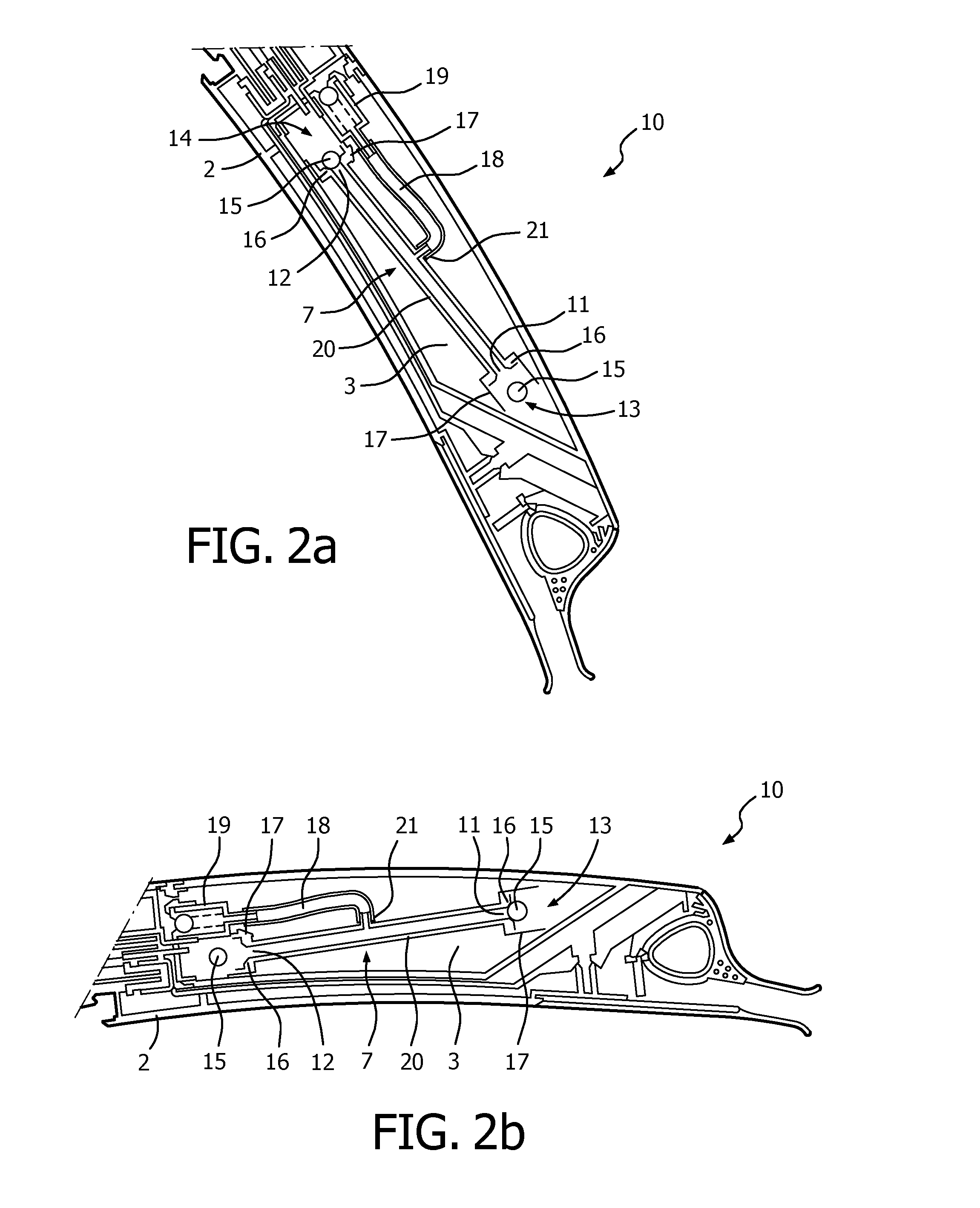
[0028]Embodiments of the invention will now be described, by way of example only, with reference to FIGS. 2 to 5 of the accompanying drawings.

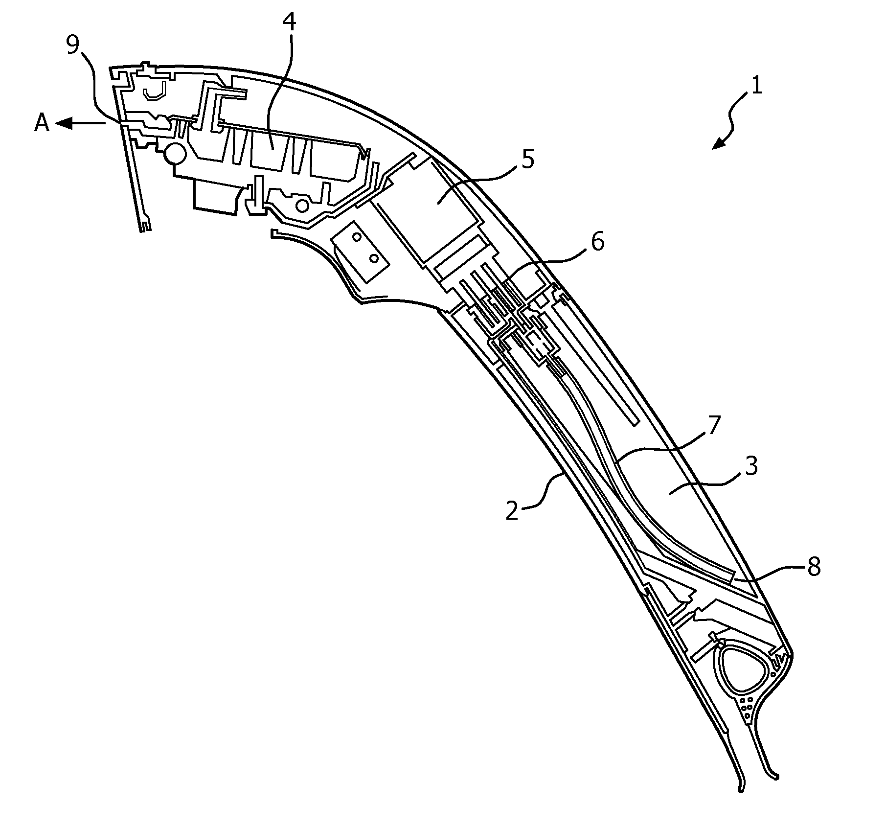
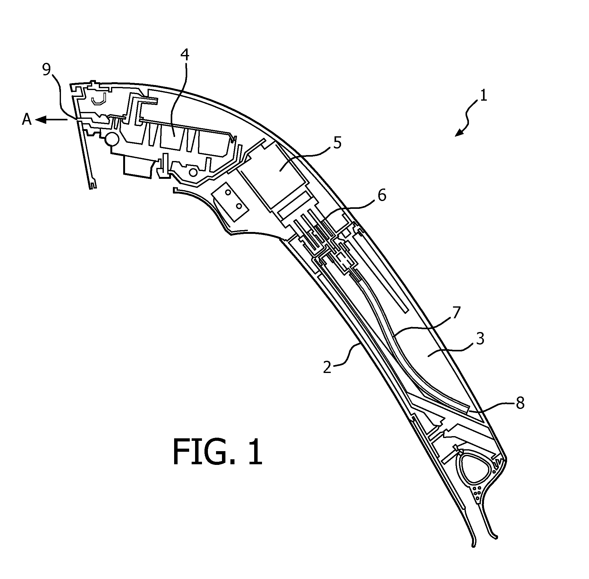
[0029]There is shown in FIGS. 2a and 2b a partial view of a first embodiment of a hand-held appliance 10 that is capable of generating steam and which comprises a housing 2 and a reservoir 3, similar to the conventional hand-held steamer 1 described with reference to FIG. 1 above. However, the portion 7 of the tube 6 (see FIG. 1) that extends into the reservoir 3 now has two tube inlets 11, 12 which are positioned at opposite ends of the reservoir 3. A valve assembly 13, 14 is positioned at each inlet 11, 12. When the hand-held steamer 10 is positioned in the orientation shown in FIG. 2a, i.e. in the same orientation as the hand-held steamer 1 shown in FIG. 1, inlet 11 is lowest and will be submerged in any water contained in the reservoir 3. The valve assembly 13 associated with the inlet 11 will then be in an open position to allow water to ...


PUM

PropertyMeasurementUnit
Weightaaaaaaaaaa
Flow rateaaaaaaaaaa

Abstract

The present application relates to a hand-held appliance comprising a housing including a reservoir to contain water and a tube to convey water from the reservoir for delivery to a surface. The tube extends into the reservoir and comprises multiple tube inlets spaced from each other within the reservoir so that, when the reservoir contains water, a tube inlet is submerged irrespective of the orientation of the housing. In one embodiment, the tube inlet comprises a separate valve assembly associated with each tube inlet so that a valve assembly associated with a submerged tube inlet opens to allow flow of water through that tube inlet and a valve assembly associated with a non-submerged tube inlet closes to prevent the flow of air through said non-submerged tube inlet. In an alternate embodiment, the appliance may be provided with a single valve member that allows water to flow through the valve assembly via a first opening, whilst also preventing the flow of air through the valve assembly through a second opening.

Description

FIELD OF THE INVENTION[0001]The present invention relates to a hand-held appliance in which a water reservoir is mounted within a housing that is held in the hand and which has an outlet or nozzle to discharge fluid or steam onto a surface, such as a garment, a fabric article such as a curtain or fabric covered items of furniture. The hand-held appliance of the invention may also be used to clean solid surfaces such as floors or counter tops by the application of steam and / or fluid to the surface.BACKGROUND OF THE INVENTION[0002]A conventional hand-held garment steamer 1 is illustrated in FIG. 1, and comprises a housing 2 containing a water tank or reservoir 3 and a heating chamber 4. Water is delivered from the reservoir 3 to the heating chamber 4 via a delivery system comprising a pump 5 and a tube 6 that has a portion 7 which extends into the reservoir 3 and which has an inlet 8 at its free end for the flow of water into the portion 7 of the tube 6 and along the tube 6 into the h...

Claims


Application Information

Patent Timeline
IPC IPC(8): D06F87/00A47L11/34D06F75/14
CPCD06F87/00A47L11/34D06F75/14
Inventor CHOO, BAN NEECHING, BOON KHIAN
Owner KONINKLJIJKE PHILIPS NV
Why Eureka
Try Eureka