Coil arrangement having two coils

Inactive Publication Date: 2015-12-10
ZF FRIEDRICHSHAFEN AG
View PDF7 Cites 2 Cited by
  • Summary
  • Abstract
  • Description
  • Claims
  • Application Information

AI Technical Summary

Benefits of technology

[0025]The production method according to the invention for the above-mentioned coil arrangement according to the invention is characterized by a first production step, in which the first, radially inner coil is wound, and by a second production step, in which the second, radially outer coil is wound, and by a third production step, in which the first coil is electrically connected to the second coil. The production steps are preferably carried out staggered

Problems solved by technology

A disadvantage to these known sensors is that they have a very complex design.
It has been found that a position sensor h

Method used


Image

  • Coil arrangement having two coils
  • Coil arrangement having two coils
  • Coil arrangement having two coils

Examples


Embodiment Construction

[0035]In the Figures, the same components, or at least those components having the same function, are provided with the same reference characters.

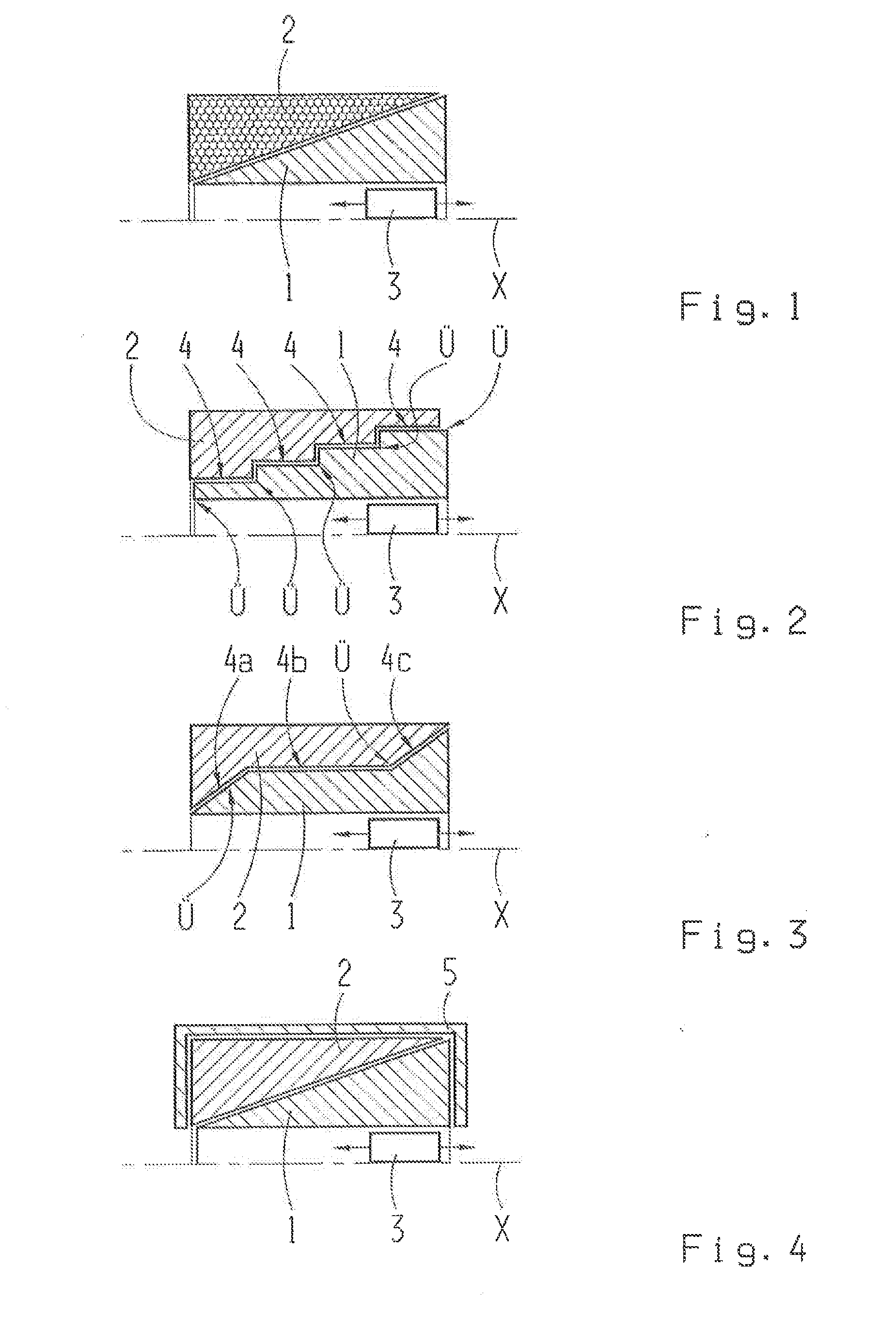
[0036]FIGS. 1, 2 and 3 each show a longitudinal section along the coil longitudinal direction X of the coil arrangement having a first coil 1 and a second coil 2. For the sake of clarity, the lower half of the coils 1, 2 is not depicted. The coil longitudinal direction X preferably simultaneously forms an axis of symmetry of the coil arrangement. The coils 1, 2 thus form a common hollow cylinder about the coil longitudinal direction X. The first coil 1 forms a radially inner coil, while the second coil 2 forms a radially outer coil. The coils 1, 2 are thus disposed in one another, substantially coaxially to the coil longitudinal direction X. The individual windings of the coil 2 are depicted in the second coil 2 by way of example. The windings run orthogonally with respect to the drawing plane of the Figures. As shown, the windings of the ...


PUM

PropertyMeasurementUnit
Densityaaaaaaaaaa
Magnetic fluxaaaaaaaaaa

Abstract

A cod arrangement, in particular for a position sensor, has a first coil (1) and a second coil (2) which are electrically connected to one another and disposed substantially coaxially relative to one another. The first coil (1) has a winding density that increases in the longitudinal direction (X) of the coil arrangement, and the second coil (2) has a winding density that decreases in the longitudinal direction (X) of the coil arrangement. In addition, the invention relates to a position sensor having such a coil arrangement and a production method for such a coil arrangement.

Description

[0001]This application is a National Stage completion of PCT / EP2013 / 076833 filed Dec. 17, 2013, which claims priority from German patent application serial no. 10 2013 200 698.5 filed Jan. 18, 2013.FIELD OF THE INVENTION[0002]The invention relates to a coil arrangement having a first coil and a second coil, which are electrically connected to one another, and which are disposed substantially coaxially relative to one another, wherein the first coil has a winding density that increases in the longitudinal direction of the coil arrangement. Furthermore, the invention relates to a position sensor, as well as to a production method for the coil arrangement.BACKGROUND OF THE INVENTION[0003]Various embodiments of contactless linear position sensors are known. The most important representatives use magnetic fields for sensing. These include sensors that use the Hall effect or the law of induction. The latter, in turn, can be subdivided into two groups according to the principle by which su...

Claims


Application Information

Patent Timeline
IPC IPC(8): G01D5/20H01F5/04H01F41/06
CPCG01D5/2046Y10T29/49073H01F5/04H01F41/06G01D5/2013
Inventor GRAF, ALEXANDERWEINL, FLORIANPANTKE, MICHAEL
Owner ZF FRIEDRICHSHAFEN AG
Why Eureka
Try Eureka