DC-DC Converter Apparatus

Active Publication Date: 2015-12-10
HITACHI ASTEMO LTD
View PDF9 Cites 23 Cited by
  • Summary
  • Abstract
  • Description
  • Claims
  • Application Information

AI Technical Summary

Benefits of technology

[0011]According to the invention, an electromagnetic noise from a transformer is shielded by a metal frame placed between a control circuit board assembly and the transformer. Further, the transformer i

Problems solved by technology

When a temperature is increased due to

Method used


Image

  • DC-DC Converter Apparatus
  • DC-DC Converter Apparatus
  • DC-DC Converter Apparatus

Examples


Embodiment Construction

External Appearance of DC-DC Converter Apparatus

[0026]Hereinafter, an embodiment of a DC-DC converter apparatus of the invention will be described with reference to drawings.

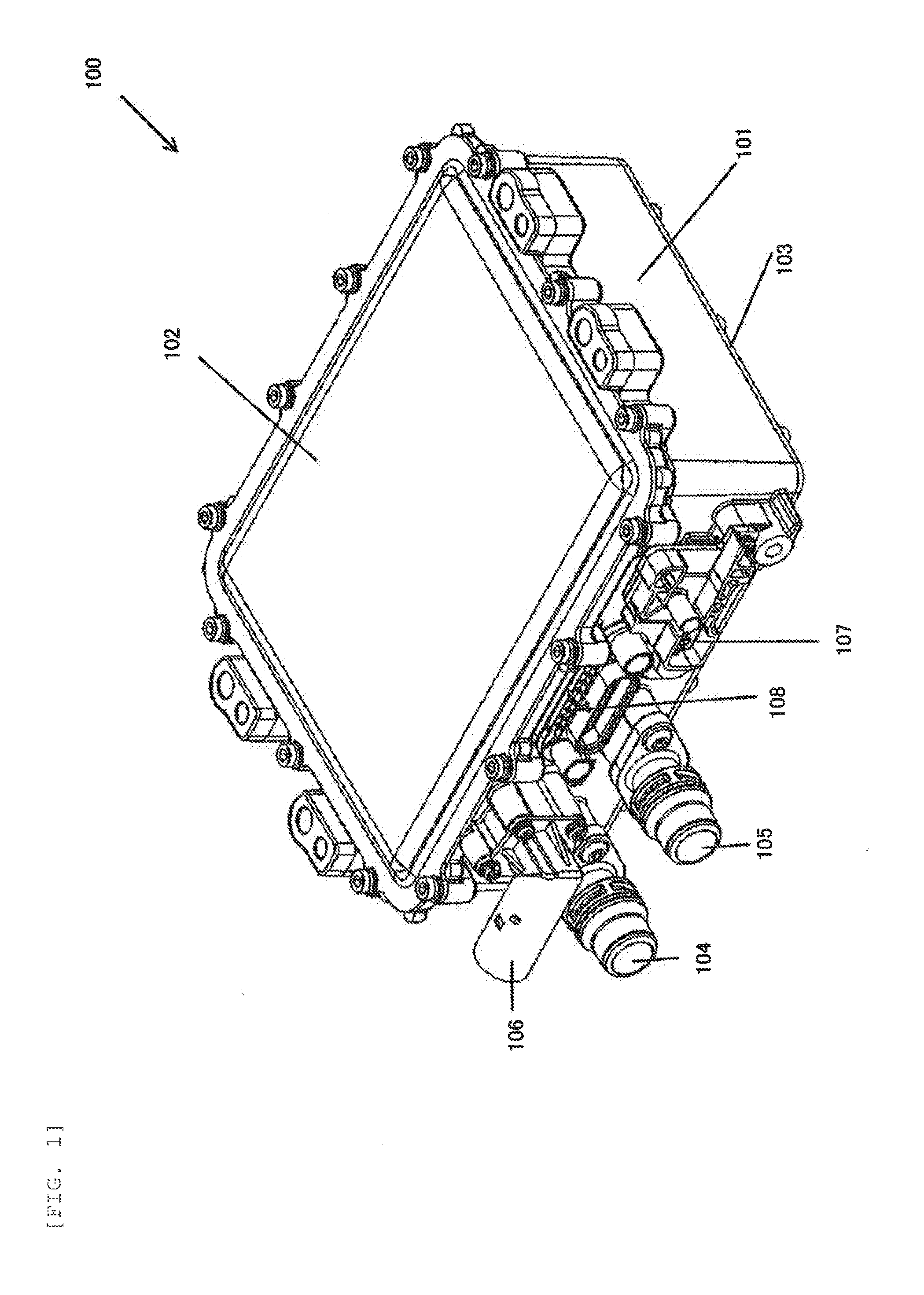
[0027]FIG. 1 is an external appearance perspective view of a DC-DC converter apparatus 100 of the invention.

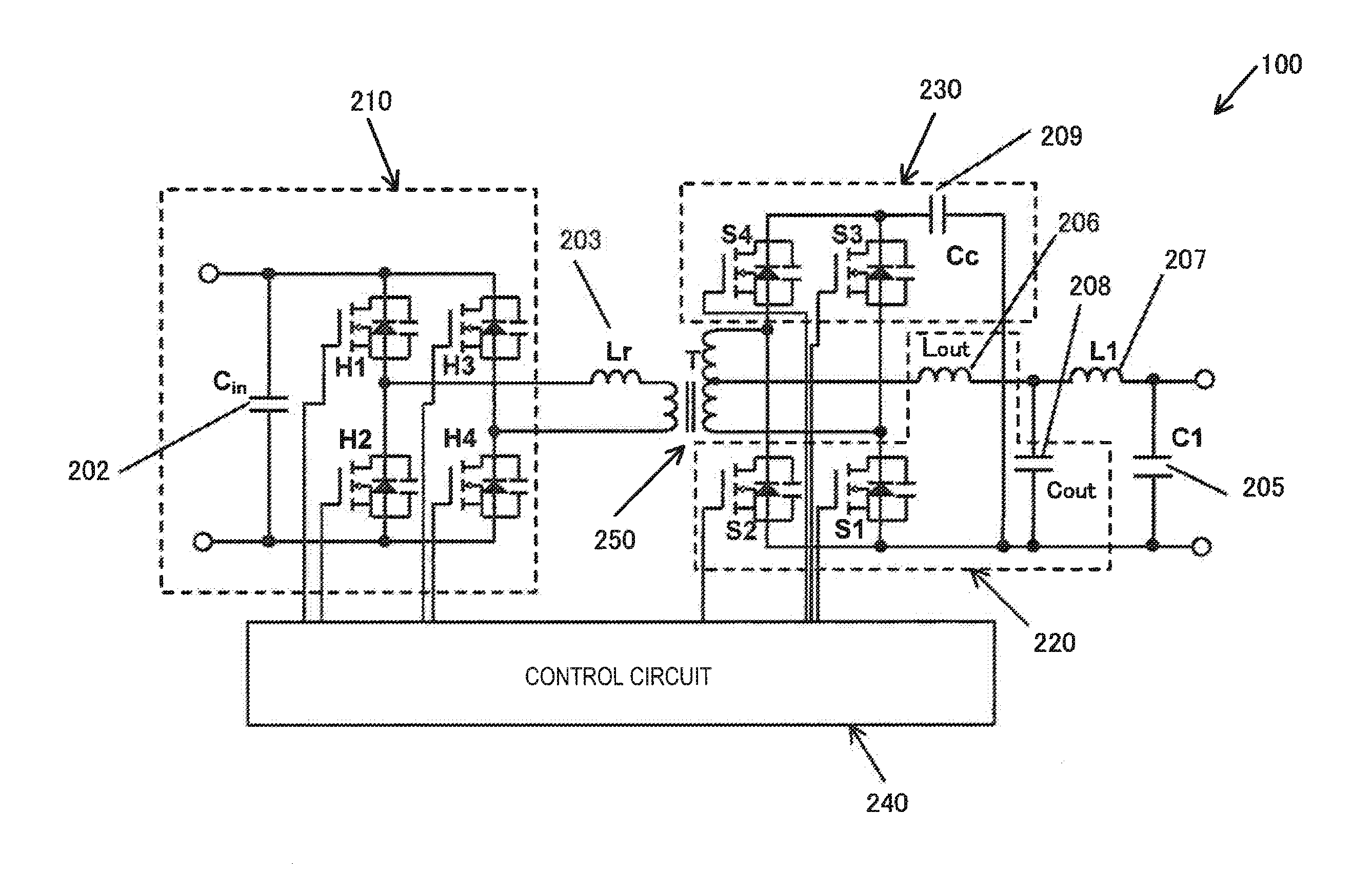
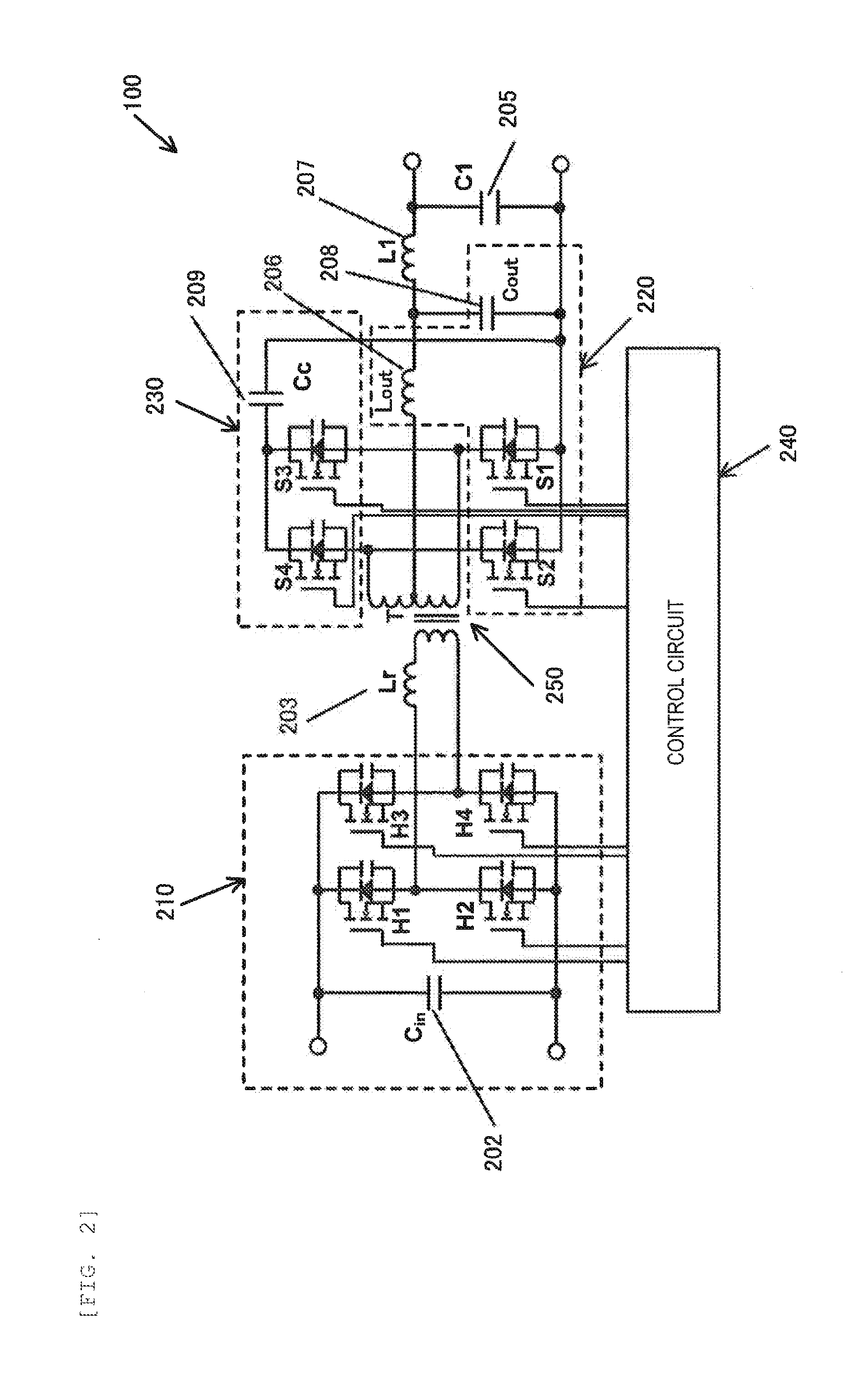
[0028]The DC-DC converter apparatus 100 is applied to an electric vehicle, a plug-in hybrid vehicle, and the like. The vehicle includes a low voltage storage battery for operating auxiliaries such as a light and a radio. The DC-DC converter apparatus 100 performs power conversion from a high voltage storage battery to the low voltage storage battery or performs power conversion from the low voltage storage battery to the high voltage storage battery.

[0029]A circuit for performing the power conversion is housed in a case 101.

[0030]An upper surface lid 102 is attached on an upper side of the case 101 by fastening members such as bolts. A bottom portion 101a (see FIG. 11) is integrally provided on a lower sid...


PUM


Abstract

Objects of the invention are not to receive influence of an electromagnetic noise from a transformer and to reduce a possibility of breakage caused by shock or vibration. In a DC-DC converter apparatus of the invention, a shielding metal frame 300 is placed between a transformer 250 and a control circuit board assembly 240A housed in a case 101. A plate spring 311 attached to the metal frame 300 is pressed to cores 251 of the transformer 250 to fix the transformer 250 to a bottom portion 101a of the case 101. Heat generated from the transformer 250 is transmitted to the metal frame 300 and the bottom portion 101a of the case 101 and is then radiated.

Description

TECHNICAL FIELD [0001]The present invention relates to a DC-DC converter apparatus and particularly relates to a DC-DC converter apparatus including a transformer for converting an AC high voltage into an AC low voltage.BACKGROUND ART[0002]An electric vehicle and plug-in hybrid vehicle include an inverter device for performing motor drive with the use of a high voltage storage battery for power drive and a low voltage storage battery for operating auxiliaries such as lights of the vehicles and a radio. Such a vehicle includes a DC-DC converter apparatus for performing power conversion from a high voltage storage battery to a low voltage storage battery or performing power conversion from the low voltage storage battery to the high voltage storage battery.[0003]The DC-DC converter apparatus includes a high-voltage side switching circuit for converting a DC voltage having a high voltage into an AC voltage, a transformer for converting an AC high voltage into an AC low voltage, a low-v...

Claims


Application Information

Patent Timeline
IPC IPC(8): H02M3/335H05K7/14H02M1/44
CPCH02M3/33507H05K7/1432H02M1/44H02M3/28H02M3/33576H05K7/14322
Inventor NAKAZAWA, TATSUYAYAMASHITA, YOSHIHARUSHINOHARA, HIDENORIGOTO, AKIHIRO
Owner HITACHI ASTEMO LTD
Why Eureka
Try Eureka