System and method for securing free end of wound cable

Inactive Publication Date: 2015-12-17
WINDAK
View PDF2 Cites 10 Cited by
  • Summary
  • Abstract
  • Description
  • Claims
  • Application Information

AI Technical Summary

Benefits of technology

[0009]In yet another aspect, the invention is embodied by a method for securing the free end of an elongate, flexible component wound onto a spool. The method includes providing a spooling machine having at least one spooling head for winding a length of the elongate, flexible component onto the spool and providing a stretch wrap applicator operably coupled with the at least one spooling head for applying stretch wrap to the elongate, flexible component wound on the spool. The stretch wrap applicator includes a pulling clamp and a length of the stretch wrap. The method further includes moving the pulling clamp from an initial position around a free end of the elongate, flexible component wound on the spool. The method further includes gripping a starting end of the stretch wrap with the pulling clamp. The method further includes moving the pulling clamp and the starting end of the stretch wrap back to the initial position with the stretch wrap disposed between the free end of the elongate, flexible component and outermost windings of the elongate, flexible component. The method further includes moving the pulling clamp in a downward direction so as to pinch the stretch wrap within a ni

Problems solved by technology

However, a number of disadvantages, deficiencies and problems are associated with the automatic stretch wrap applicator of the MGS/Hall spooling machine.
The MGS/Hall stretch wrap applicator requires an excessive number of separate components, which results in high cost and reduced reliability of the applicator.
Therefore, the relatively thin layer of stretch wrap can slip on a wound cable having an excessively smooth or slick ja

Method used


Image

  • System and method for securing free end of wound cable
  • System and method for securing free end of wound cable
  • System and method for securing free end of wound cable

Examples


Embodiment Construction

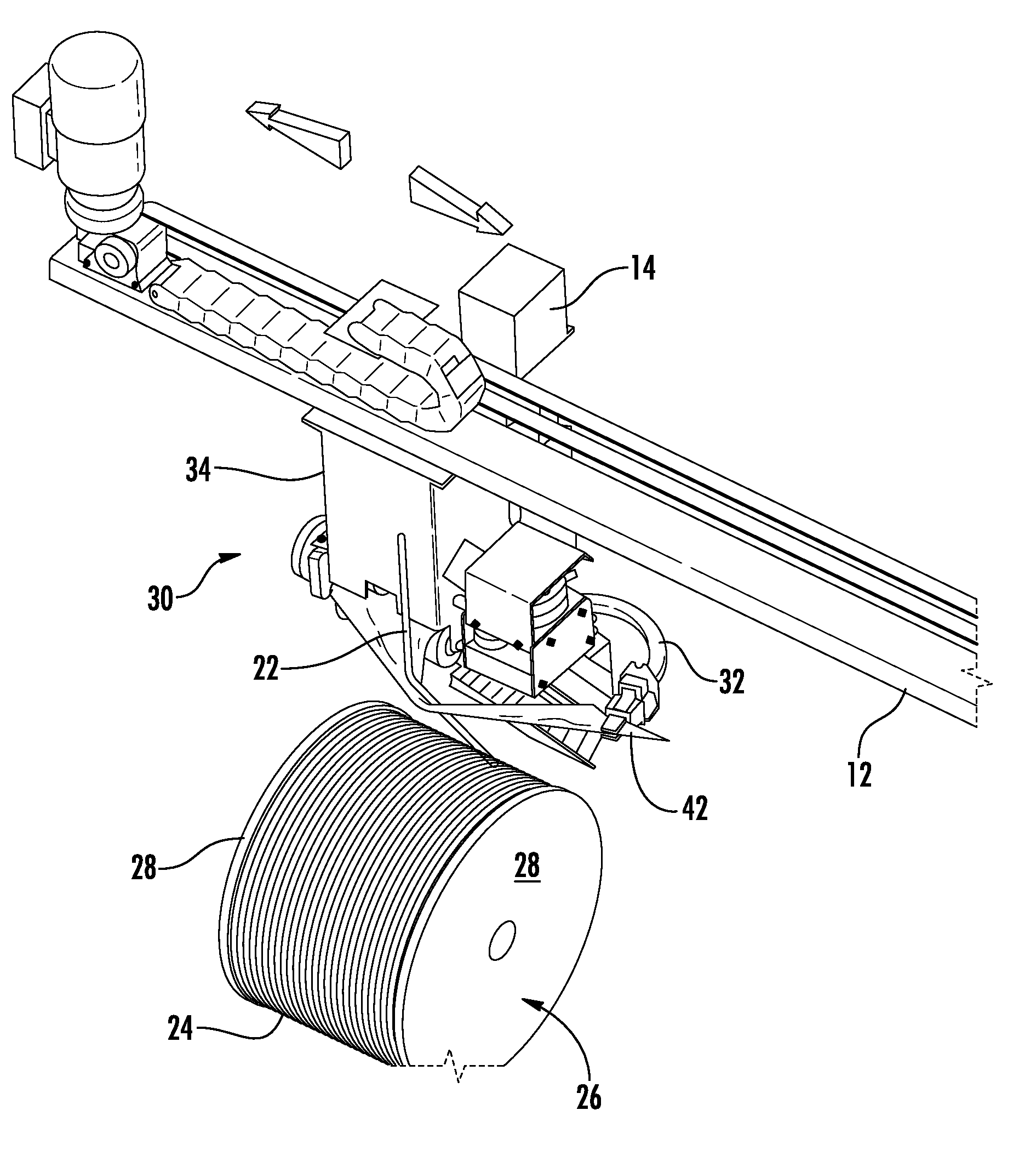
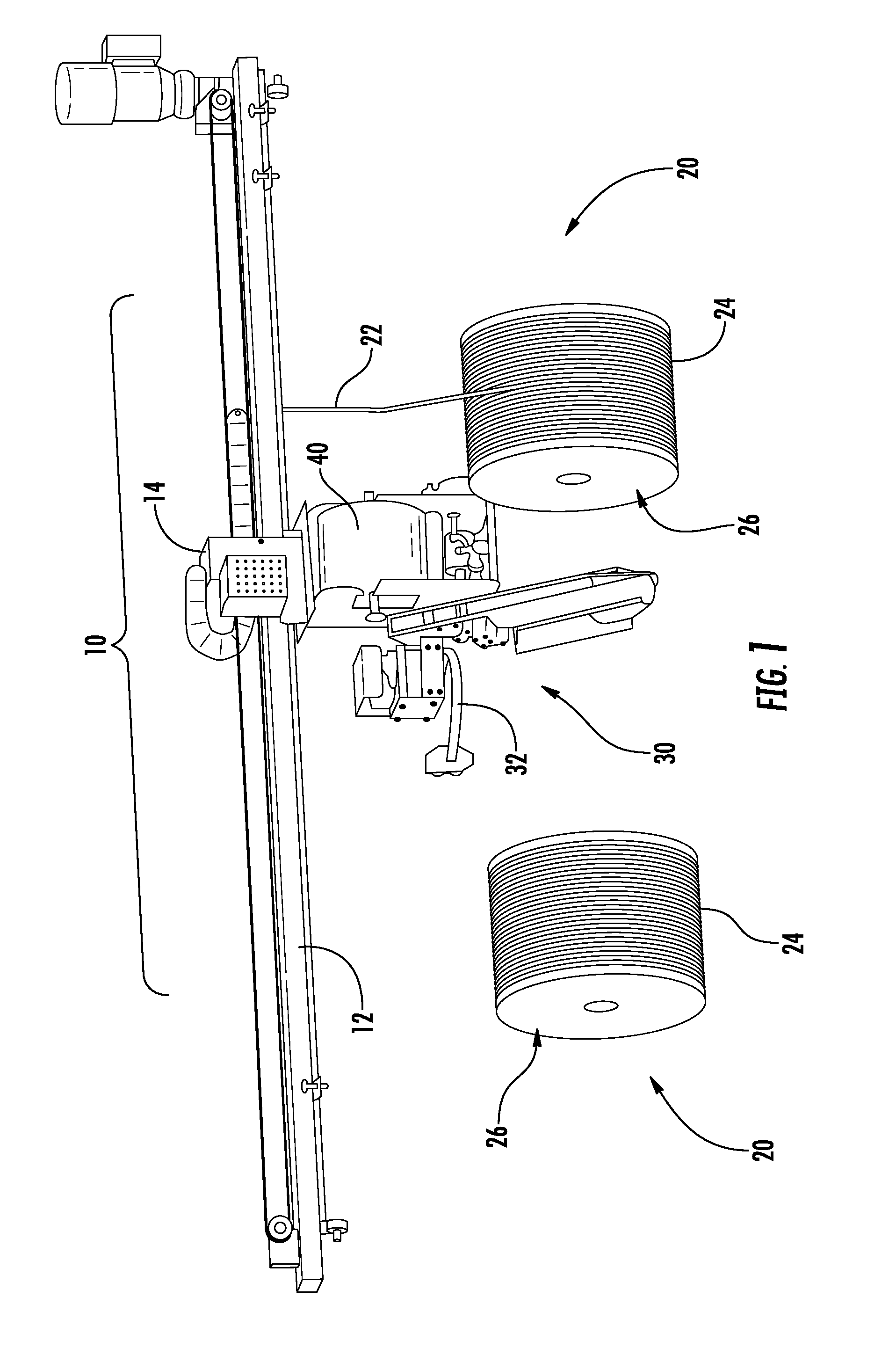
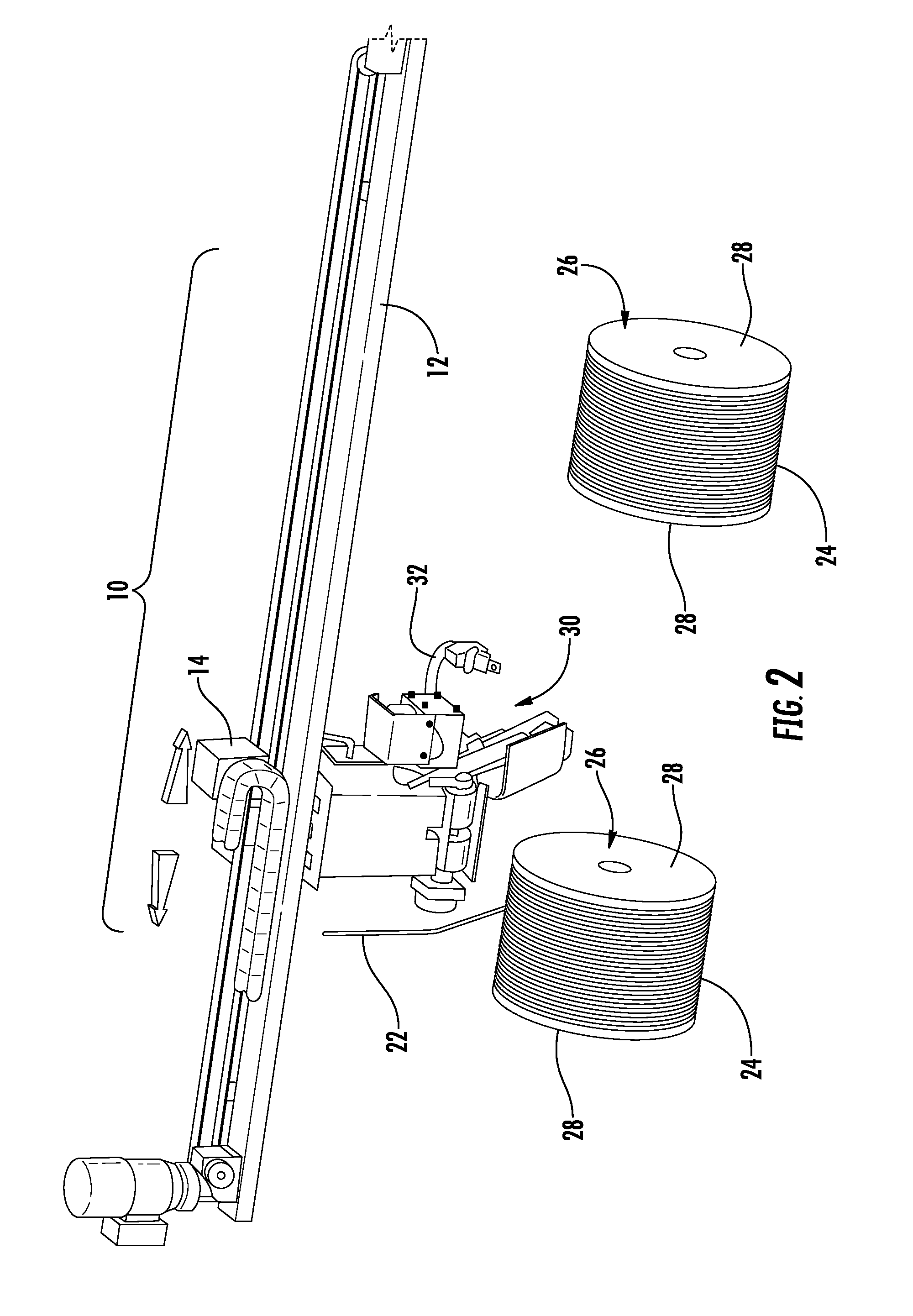
[0030]Referring now to the accompanying drawings, in which like reference characters in the drawing figures refer to the same or similar parts, a spooling machine, indicated generally at 10, having two spooling heads, each indicated generally at 20 with the corresponding winder not depicted for purposes of clarity, and a stretch wrap applicator, indicated generally at 30, is shown in FIGS. 1-14. The single stretch wrap applicator 30 is configured for and operable to secure a free end 22 of a length of cable 24 wound onto a spool 26 by wrapping the spool of wound cable with stretch wrap 40 (see e.g., FIGS. 8-13). In the exemplary embodiments shown and described herein, the stretch wrap applicator 30 is movable transversely relative to the two spooling heads 20 of the spooling machine 10 so that the single stretch wrap applicator is configured for and operable to service both spooling heads. However, as will be readily appreciated by those skilled in the art, if desired each spooling ...


PUM

PropertyMeasurementUnit
Lengthaaaaaaaaaa
Angleaaaaaaaaaa
Flexibilityaaaaaaaaaa

Abstract

A system for securing a free end of a cable wound on a spool includes a spooling machine having at least one spooling head for winding a length of the cable onto the spool and a stretch wrap applicator for securing the free end of the cable on the spool with stretch wrap that is pinched between the free end of the cable and the outermost windings of the cable wound on the spool. A stretch wrap applicator for a spooling machine having at least one spooling head includes a housing, a roll of stretch wrap disposed within the housing and a pulling clamp for gripping and pulling a starting end of the stretch wrap so as to position the stretch wrap between a spool of wound cable having outermost windings and a free end of the cable wound on the spool. A method for securing the free end of a cable wound on a spool includes providing the spooling machine and the stretch wrap applicator, moving the pulling clamp from an initial position around a free end of the cable, gripping a starting end of the stretch wrap, moving the pulling clamp and the stretch wrap back to the initial position with the stretch wrap disposed between the free end and the outermost windings of the cable and moving the pulling clamp in a downward direction so as to pinch the stretch wrap within a nip defined between the outermost windings and the free end of the cable.

Description

CROSS-REFERENCE To RELATED APPLICATION[0001]This application claims the benefit of priority to U.S. Provisional Patent Application No. 62 / 011,013 filed on Jun. 11, 2014, the entire disclosure of which is incorporated herein by reference.FIELD OF THE INVENTION[0002]The present invention relates generally to systems, apparatus and methods for securing the free end of wound cable. More particularly, the invention is a system and method for securing the free end of a length of an elongate, flexible cable that is wound onto a spool by a spooling machine. The free end of the cable is secured using stretch wrap that is automatically applied to a spool of wound cable as the cable is being cut so that the leading end of the stretch wrap is nipped between the spool of wound cable and the free end of the cable. In an exemplary embodiment, the stretch wrap system is mounted horizontally and movable in a transverse direction to service at least two cable spooling stations on a spooling machine.B...

Claims


Application Information

Patent Timeline
IPC IPC(8): B65B53/00B65B11/54B65B61/06B65B45/00B65B11/02B65B41/12
CPCB65B53/00B65B11/02B65B11/54B65B61/06B65B45/00B65B41/12B65B11/025B65B11/04B65B25/24B65B2210/16B65H75/285
Inventor SHELANDER, DANIEL L.
Owner WINDAK
Why Eureka
Try Eureka