Atomizer, Combustion Device Including Atomizer, and Gas Turbine Plant

Active Publication Date: 2015-12-17
MITSUBISHI POWER LTD
View PDF9 Cites 4 Cited by
  • Summary
  • Abstract
  • Description
  • Claims
  • Application Information

AI Technical Summary

Benefits of technology

[0016]According to the present invention, an atomizer capable of promoting atomization of the spray fluid and capable of suppressing t

Problems solved by technology

On the other hand, because the rate of the air to the fuel is high, stable combustion range is limited.
Also, when the combustion temperature is low, CO and particulate matters are liable to be generated as unburnt carbon.
Also in the twin-fluid atomization method, even when the supply amount of the liquid fuel may change, variation in atomizing performance is small.
However, the spray fluid and the spray medium are liable to be separated because of the difference in density.
Particularly, in the mixing chamber where the volume is large and the flow speed of the fluid mixture drops, the spray fluid and the spray medium are separated at a portion with low flow speed, and local variance of the mixing ratio of the spray fluid and the spray medium is liable to become large.
In this case, there is a problem that stirring mixing in the mixing chamber does not advance, and atomization does not advance.
F

Method used


Image

  • Atomizer, Combustion Device Including Atomizer, and Gas Turbine Plant
  • Atomizer, Combustion Device Including Atomizer, and Gas Turbine Plant
  • Atomizer, Combustion Device Including Atomizer, and Gas Turbine Plant

Examples


first embodiment

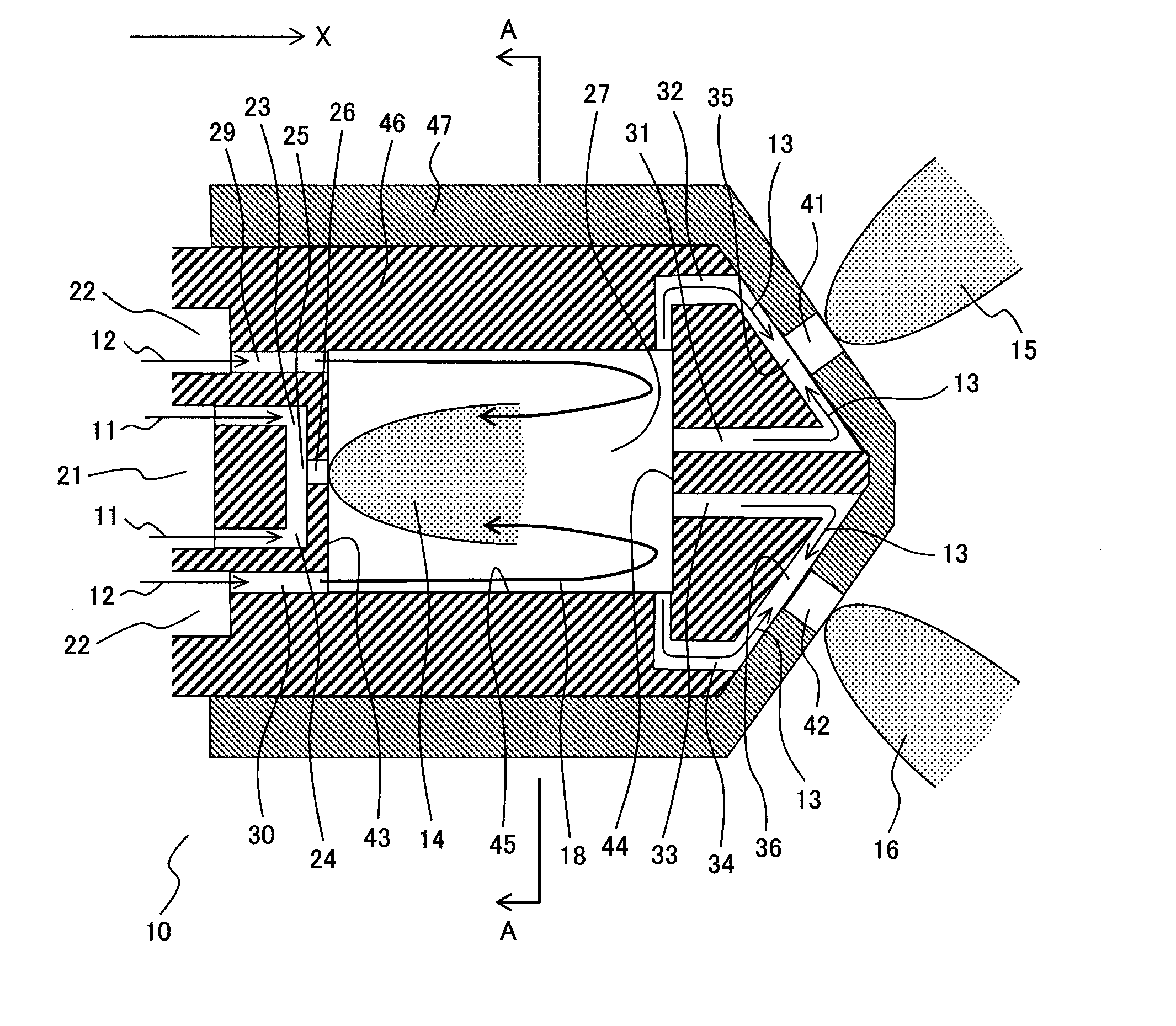
[0030]An atomizer 10 according to the first embodiment of the present invention will be explained with reference to FIGS. 1-8.

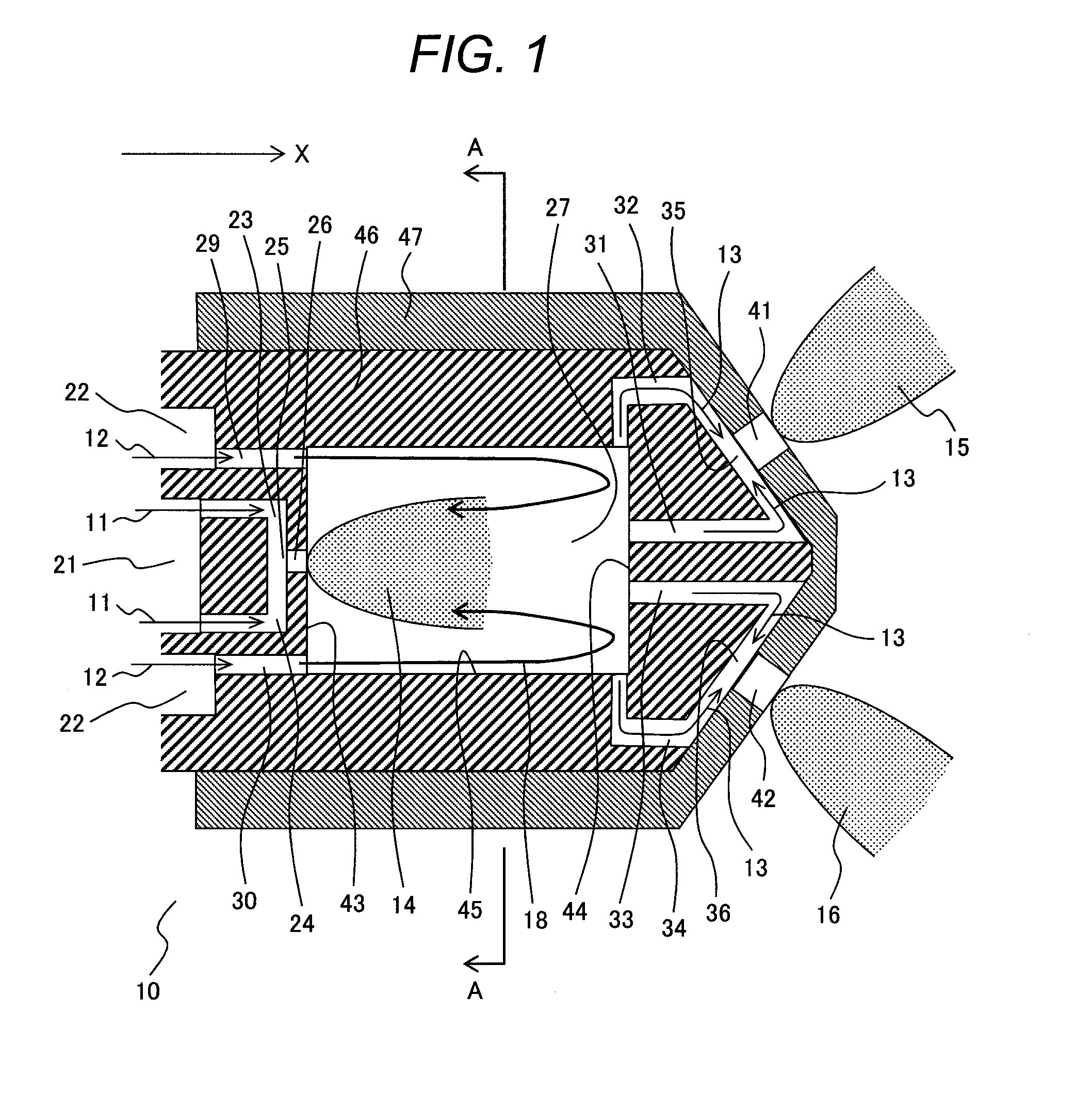
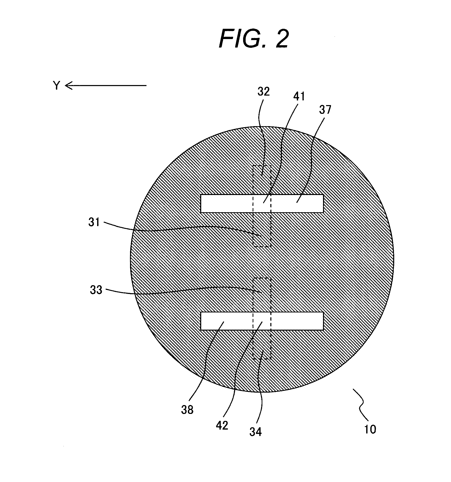
[0031]FIG. 1 is a cross-sectional view of a front end section of the atomizer 10 according to the present embodiment along the axial direction (X-direction). In FIG. 1, X-direction is the axial direction of the atomizer 10 and is the supply direction of the spray fluid. FIG. 2 is a front view when the atomizer 10 of FIG. 1 is viewed from the downstream side of the supply direction of the spray fluid. FIG. 3 is a cross-sectional view of the atomizer 10 taken along the cut line A-A of FIG. 1 and is a cross-sectional view of the atomizer 10 as viewed from the downstream side of the supply direction of the spray fluid at a position of a mixing chamber 27 of the atomizer 10. In FIGS. 2, 3, Y-direction is the radial direction of the atomizer 10.

[0032]FIG. 4 is a cross-sectional view of a front end section of an atomizer 100 according to a conventional art along the...

second embodiment

[0083]An atomizer 50 according to the second embodiment of the present invention will be explained with reference to FIGS. 9-11.

[0084]FIG. 9 is a cross-sectional view of a front end section of the atomizer 50 according to the present embodiment along the axial direction (X-direction). In FIG. 9, X-direction is the axial direction of the atomizer 50 and is the supply direction of the spray fluid. FIG. 10 is a front view when the atomizer 50 of FIG. 9 is viewed from the downstream side of the supply direction of the spray fluid. FIG. 11 is a cross-sectional view of the atomizer 50 taken along the cut line A-A of FIG. 9, and is a cross-sectional view when the atomizer 50 is viewed from the downstream side of the supply direction of the spray fluid at the position of the mixing chamber 27 of the atomizer 50. In FIGS. 10, 11, Y-direction is the radial direction of the atomizer 50.

[0085]In the atomizer 50 according to the present embodiment, the basic configuration is same as that of the ...

third embodiment

[0099]A combustion device including an atomizer, according to an embodiment of the present invention, will be explained with reference to FIG. 12. In the present embodiment, a gas turbine combustor will be exemplified as a combustion device including an atomizer. In the present embodiment, the gas turbine combustor includes the atomizer 10 shown in the first embodiment, and alternatively it may include the atomizer 50 shown in the second embodiment.

[0100]FIG. 12 is a schematic view showing a whole configuration of a gas turbine plant where a gas turbine combustion device 67 according to the present embodiment is installed. The gas turbine plant shown in FIG. 12 includes a compressor 66, a gas turbine combustor 67, a turbine 68, and a generator 69. The compressor 66 compresses air to generate high pressure combustion air 61 and supplies the high pressure combustion air 61 to the gas turbine combustor 67. The gas turbine combustor 67 is a combustion device that introduces the combusti...


PUM


Abstract

An atomizer of the invention includes a mixing chamber, spray fluid flow passages supplying a spray fluid to the mixing chamber, a spray medium flow passage supplying a spray medium to the mixing chamber, outlet holes spraying a fluid mixture of the spray fluid and the spray medium, and fluid mixture flow passages connecting the mixing chamber and the outlet holes to each other. The fluid mixture flowing through each of the fluid mixture flow passages joins with each other at a joining section and is sprayed from the outlet hole. The mixing chamber includes a middle ejection hole spraying the spray fluid to the mixing chamber. The middle ejection hole is arranged at a joining section of the spray fluid flow passages. The spray fluid flowing through the spray fluid flow passages joins with each other at the joining section and is sprayed from the middle ejection hole.

Description

CLAIM OF PRIORITY[0001]The present application claims priority from Japanese Patent Application JP 2014-121071 filed on Jun. 12, 2014, the content of which is hereby incorporated by reference into this application.FIELD OF THE INVENTION[0002]The present invention relates to an atomizer and a combustion device including the atomizer, and relates more specifically to an atomizer of a twin-fluid atomization method which atomizes liquid fuel (spray fluid) using gas (spray medium) and a combustion device including the atomizer.BACKGROUND OF THE INVENTION[0003]In the combustion device such as a combustor of a gas turbine, it is required to achieve both of diversification of fuel allowing to cope with various kinds of fuel and improvement of environmental performance.[0004]With respect to diversification of fuel, in a part of the gas turbines, a so-called dual fuel combustor is employed which uses a liquid fuel such as light oil and heavy oil A in addition to fuel gas represented by natura...

Claims


Application Information

Patent Timeline
IPC IPC(8): F02C7/22
CPCF02C7/22F23R3/28F23D11/102F23D11/38F23R3/286F02C3/30F23R3/30F02C7/222
Inventor OKAZAKI, HIROFUMIORII, AKIHITO
Owner MITSUBISHI POWER LTD
Why Eureka
Try Eureka