
System and method for coordinated control of agricultural vehicles

a technology for agricultural vehicles and coordination, applied in vehicle position/course/altitude control, process and machine control, instruments, etc., can solve the problems of increasing the cost associated with the harvesting process, and reducing the efficiency of harvesting

Active Publication Date: 2015-12-17
AUTONOMOUS SOLUTIONS +1
View PDF16 Cites 30 Cited by
  • Summary
  • Abstract
  • Description
  • Claims
  • Application Information

AI Technical Summary

Benefits of technology

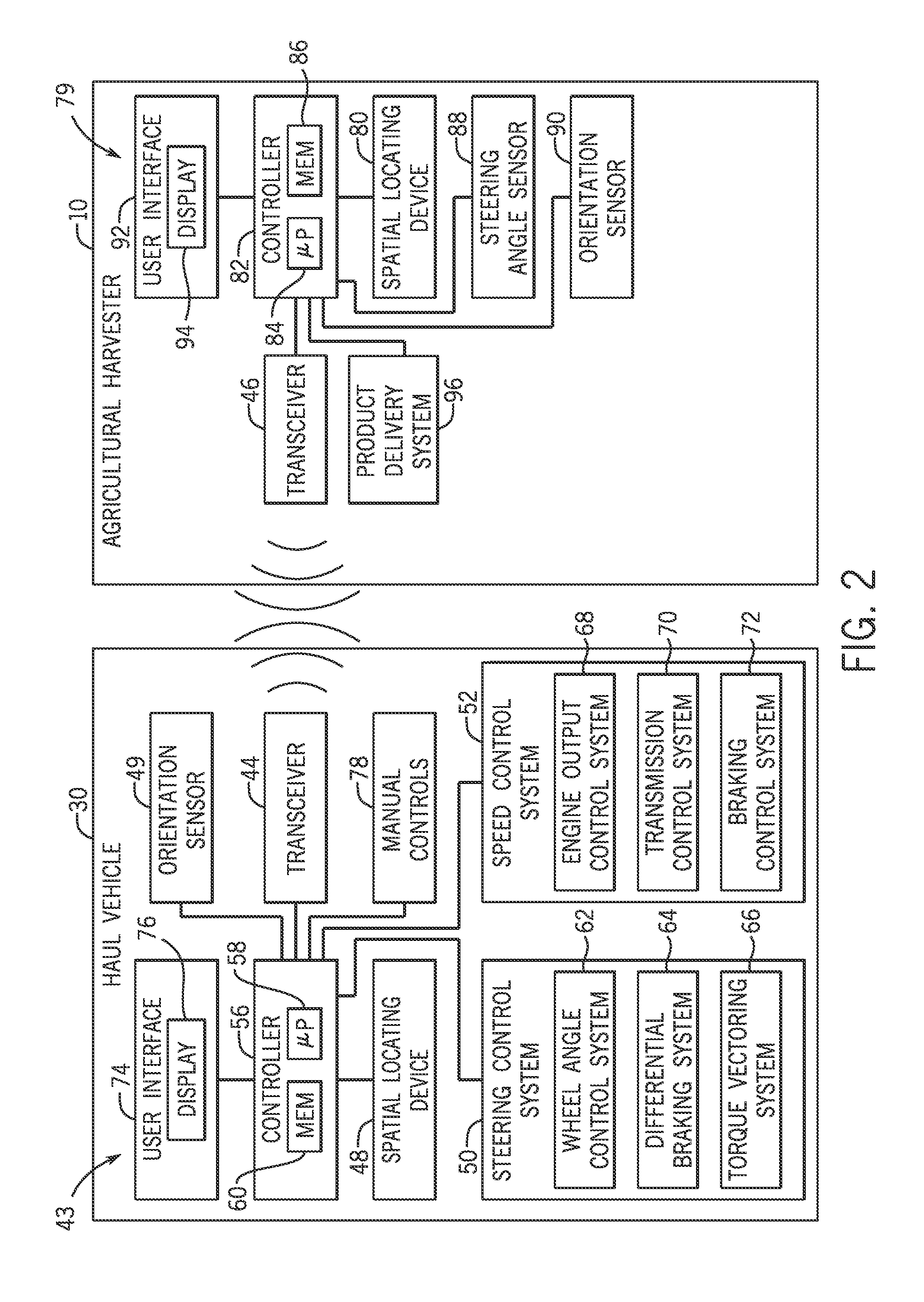
The patent describes a control system for an agricultural vehicle that uses signals from a target vehicle to automatically control the vehicle's movement. The system determines the position and velocity of the target vehicle, and then sends instructions to the vehicle's steering and speed control systems to direct it toward the target position and maintain it there. The system can also use a spatial locating device to determine the vehicle's position. The technical effect of this system is to allow the agricultural vehicle to move more efficiently and accurately, reducing the time and effort required to complete operations.

Problems solved by technology

Highly skilled drivers typically operate the haul vehicles due to the complexity associated with aligning the mobile storage compartment with the harvester and matching the speed of the harvester.
Employing such drivers may increase the costs associated with the harvesting process and / or may delay the harvesting process due to the limited availability of these drivers.
Furthermore, employing less skilled drivers to operate the haul vehicles may result in agricultural product loss due to misalignment of the mobile storage compartment with the harvester and / or mismatched operating speeds.
As a result, the efficiency of the harvesting process may be reduced.

Method used


Image

  • System and method for coordinated control of agricultural vehicles
  • System and method for coordinated control of agricultural vehicles
  • System and method for coordinated control of agricultural vehicles

Examples


Embodiment Construction

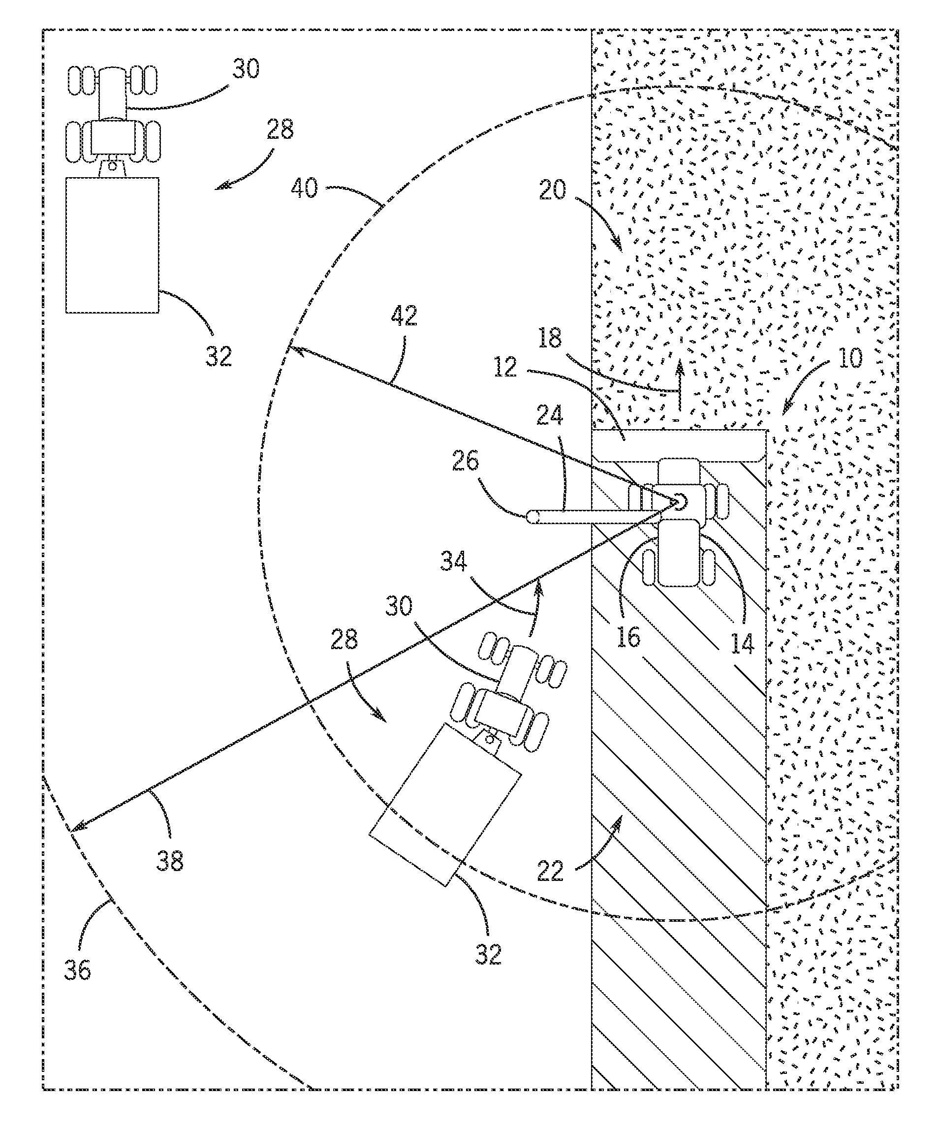
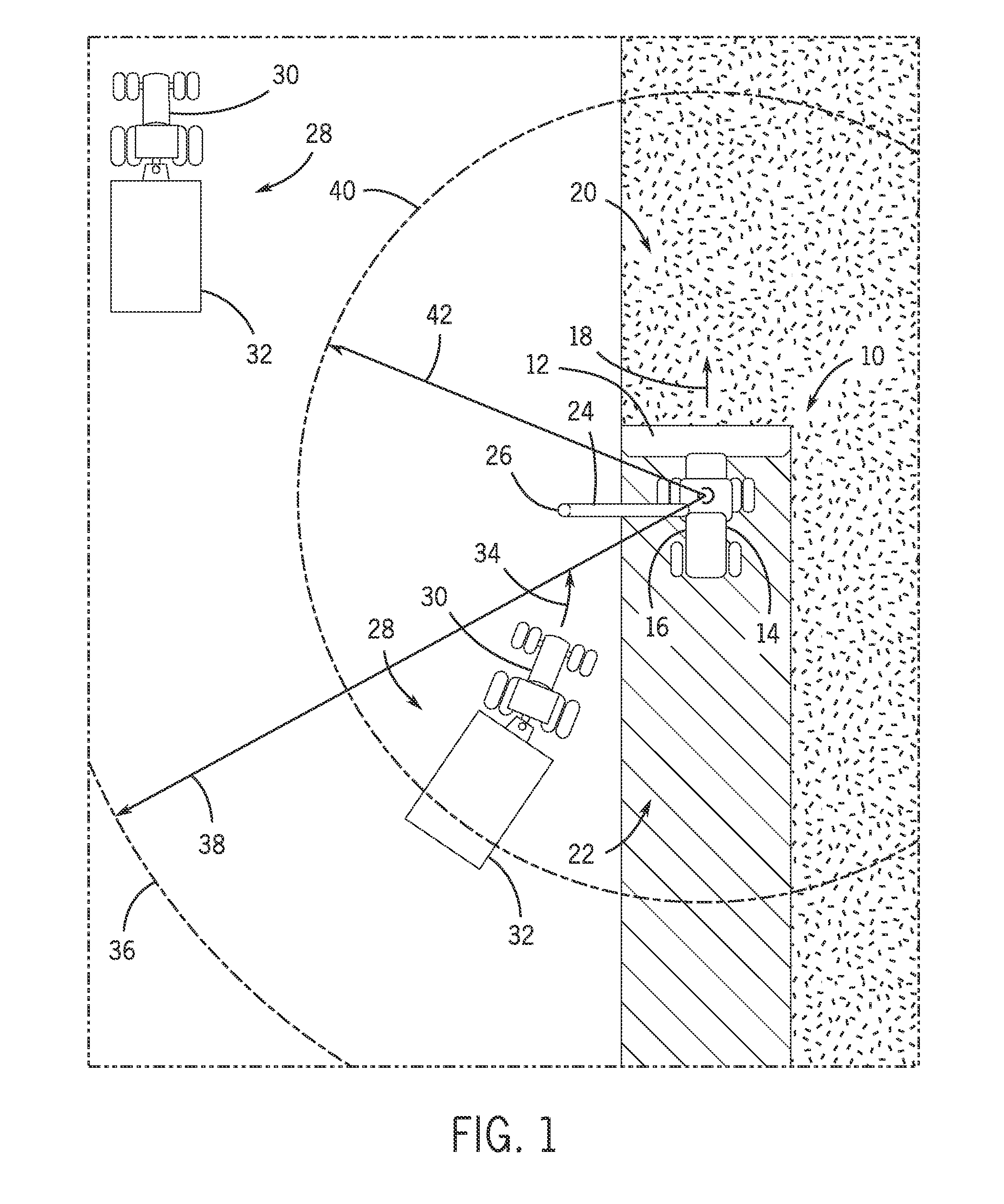
[0017]FIG. 1 is a top view of an embodiment of an agricultural harvester and an agricultural product transportation system, in which the agricultural product transportation system is configured to automatically dock with the agricultural harvester. In the illustrated embodiment, the agricultural harvester 10 includes a row of harvesting units 12 positioned on a front end of a chassis 14 and an internal storage compartment 16 coupled to the chassis 14. As the agricultural harvester 10 traverses a field in a direction of travel 18, the harvesting units 12 engage unharvested plants 20 and extract various agricultural products (e.g., corn, wheat, cotton, etc.) from the plants. These agricultural products are transferred to the internal storage compartment 16, either directly or via a processing device configured to remove undesirable portions of the agricultural products. The remaining portions of the plants remain in the field as agricultural residue 22.

[0018]As the harvester 10 traver...


PUM


Abstract

A control system for an agricultural vehicle includes a first transceiver configured to receive a first signal from a second transceiver of a target vehicle. The first signal is indicative of a first determined position and a first determined velocity of the target vehicle. The control system also includes a controller communicatively coupled to the first transceiver. The controller is configured to automatically control the agricultural vehicle by determining a target position and a target velocity of the agricultural vehicle based at least in part on the first determined position and the first determined velocity of the target vehicle, instructing an automated steering control system and an automated speed control system to direct the agricultural vehicle toward the target position, and instructing the automated steering control system and the automated speed control system to substantially maintain the target position and the target velocity upon substantially reaching the target position.

Description

CROSS REFERENCE TO RELATED APPLICATION[0001]This application claims priority from and the benefit of U.S. Provisional Application Ser. No. 62 / 011,991, entitled “SYSTEM AND METHOD FOR COORDINATED CONTROL OF AGRICULTURAL VEHICLES”, filed Jun. 13, 2014, which is hereby incorporated by reference in its entirety.BACKGROUND[0002]The invention relates generally to a system and method for coordinated control of agricultural vehicles.[0003]A harvester may be used to harvest agricultural crops, such as cotton, wheat, flax, or other crops. Generally, components (e.g., drums, spindles, blades, etc.) of the harvester remove portions of the agricultural crops from the ground. The harvester then conveys the removed portions of the agricultural crops (e.g., agricultural products) to an internal storage compartment, either directly or via a processing device configured to remove undesirable portions of the agricultural products.[0004]As the harvester traverses a field, the volume of the agricultural...

Claims


Application Information

Patent Timeline
Patent Type & Authority Applications(United States)
IPC IPC(8): G05D1/02G05D13/62
CPCG05D1/0276G05D2201/0201G05D13/62G05D1/0291A01B69/008A01B79/02A01D41/00
Inventor DOLLINGER, TYSON J.RAY, BRIAN R.RUSCIOLELLI, ADAM R.TORRIE, MITCHEL R.LEWIS, PAULHORNBERGER, MICHAEL G.MORWOOD, DANIEL J.BERKEMEIER, MATTHEW D.
Owner AUTONOMOUS SOLUTIONS
Learn More