Constant on-time or constant off-time switching power converter and control circuit thereof

a power converter and constant on-time switch technology, applied in the direction of dc-dc conversion, power conversion systems, instruments, etc., can solve the problems of high cost, large circuit size, complicated pll,

Active Publication Date: 2015-12-17
RICHTEK TECH
View PDF4 Cites 19 Cited by
  • Summary
  • Abstract
  • Description
  • Claims
  • Application Information

AI Technical Summary

Benefits of technology

[0012]In one embodiment, before the switching frequency of the power switch is aligned to the fixed switching frequency, the frequency of the clock signal is faster than the switching frequency of the power switch.

Problems solved by technology

However, if the switching frequency of the power switch is not first aligned to the given frequency, although a proper ON-time or OFF-time is calculated, the power switch may not be able to operate by the desired fixed frequency.
However, a PLL is a complicated, high cost, and large size circuit.

Method used


Image

  • Constant on-time or constant off-time switching power converter and control circuit thereof
  • Constant on-time or constant off-time switching power converter and control circuit thereof
  • Constant on-time or constant off-time switching power converter and control circuit thereof

Examples


Embodiment Construction

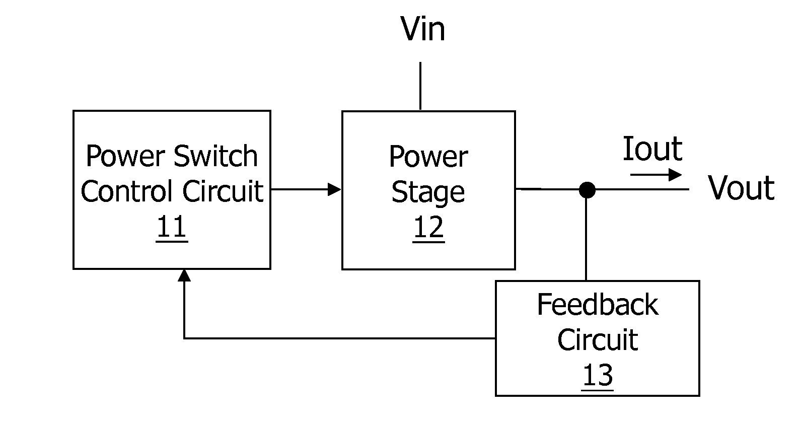
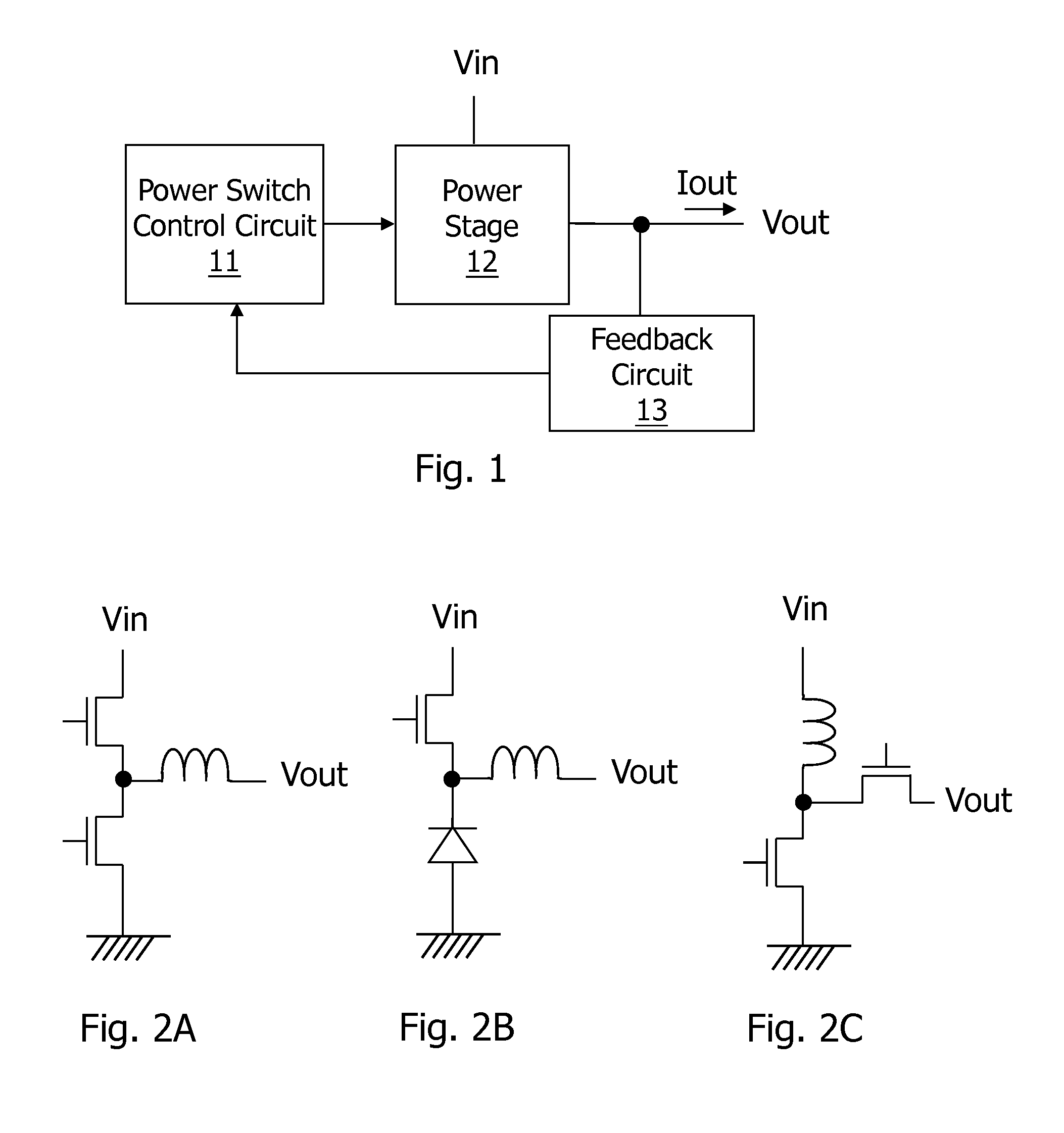
[0030]Please refer to FIG. 4, which shows an embodiment of a control circuit of a switching power converter according to the present invention. This embodiment illustrates a control circuit which is applied to a constant ON-time control mode, but as will be understood from other embodiments to be explained later, the present invention can be applied to a constant OFF-time control mode as well. The control circuit 41 in FIG. 4 replaces the power switch control circuit 11 in FIG. 1, to control at least one power switch within the power stage circuit 12. As shown in FIG. 4, the control circuit 41 includes an ON-time calculation circuit 411, a flip-flop 412, and a logic circuit 413. The ON-time calculation circuit 411 calculates a proper ON-time according to input voltage related information and output voltage related information, so that when the power switch operates according to this proper ON-time, the switching frequency can be fixed. The ON-time calculation circuit 411 can calcula...


PUM


Abstract

A constant ON-time or constant OFF-time switching power converter includes a control circuit for controlling a power switch. The control circuit includes: a constant ON-time or constant OFF-time calculation circuit, for calculating a constant ON-time or constant OFF-time; a logic circuit having inputs for receiving an output of the constant ON-time or constant OFF-time calculation circuit and a clock signal, respectively, wherein the clock signal has a frequency which is the desired fixed frequency; and a flip-flop for generating an output signal according to a set input and a reset input, wherein one of the set input and the reset input receives an output of the logic circuit, and the other one of the set input and the reset input receives a trigger signal which determines a start time of the ON-time or OFF-time.

Description

CROSS REFERENCE[0001]The present invention claims priority to U.S. 62 / 011,802, filed on Jun. 13, 2014.BACKGROUND OF THE INVENTION[0002]1. Field of Invention[0003]The present invention relates to a constant ON-time or constant OFF-time switch power converter and a control circuit thereof; particularly, the present invention relates to such a constant ON-time or constant OFF-time switch power converter which can achieve fixed-frequency control without requiring a complicated phase lock loop (PLL), and a control circuit thereof.[0004]2. Description of Related Art[0005]FIG. 1 shows a conventional switching power converter. A power switch control circuit 11 controls at least one power switch (referring to FIGS. 2A-2H) within a power stage circuit 12, to convert an input voltage Vin to an output voltage Vout, and to provide an output current Iout when it is required by a load circuit (not shown). The power stage circuit 12 is for example but not limited to a synchronous or non-synchronous...

Claims


Application Information

Patent Timeline
Patent Type & Authority Applications(United States)
IPC IPC(8): G05F1/575
CPCG05F1/575H02M1/08H02M3/156
Inventor WANG, KO-CHENG
Owner RICHTEK TECH
Why Eureka
Try Eureka