
Pourable spout with child proof mechanism

a technology of child-proof mechanism and spout, which is applied in the direction of liquid handling, closure using stoppers, instruments, etc., can solve the problems of difficult use of spout, difficult to apply enough leverage to the portion of the spout, and many times difficult to meet the new regulations

Inactive Publication Date: 2015-12-24
MINERVA MFG
View PDF3 Cites 5 Cited by
  • Summary
  • Abstract
  • Description
  • Claims
  • Application Information

AI Technical Summary

Benefits of technology

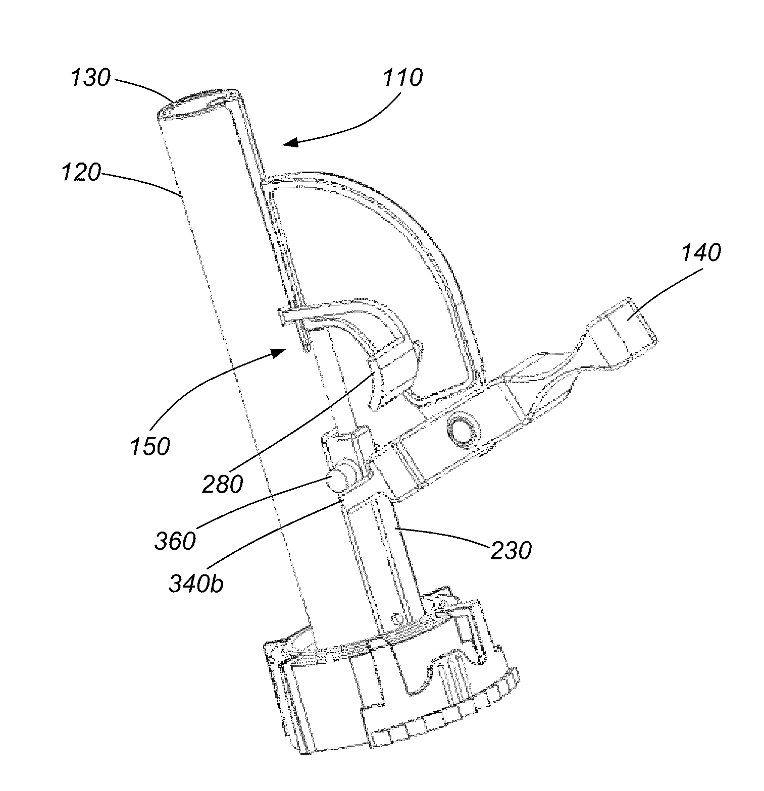
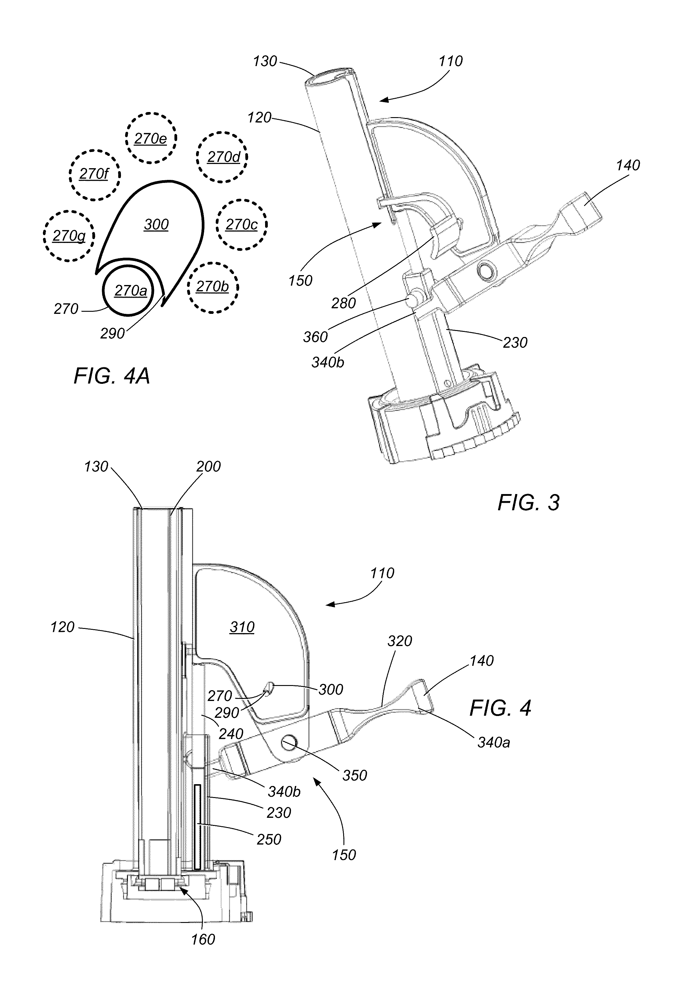
This patent describes a system and method for controlling the movement of a spout in a container. The system includes a pouring spout assembly with five conduits, a handle, and a spout lock. The spout lock prevents the second conduit from moving from a first position to a second position when engaged. The technical effect of this system is that it allows liquids and gases to be controlled as they are poured through the spout, making it easier to control the flow and preventing any accidental spills.

Problems solved by technology

Secondly fuel containers must meet the requirements of the Children's Gasoline Burn Prevention Act.
Currently available pouring spouts, which attempt to meet the new regulations, are many times difficult to use.
The difficulty arises in that they appear to require applying pressure to a portion of the pouring spout using the container into which fuel is being transferred.
This can be difficult to apply enough leverage against the portion of the spout and can be dangerous depending upon what type of container the fluids are being transferred to (e.g., is the container stable enough to use for leverage without tipping over or being damaged resulting in a spill).

Method used


Image

  • Pourable spout with child proof mechanism
  • Pourable spout with child proof mechanism
  • Pourable spout with child proof mechanism

Examples


Embodiment Construction

Definitions

[0086]Unless defined otherwise, all technical and scientific terms used herein have the same meaning as commonly understood by one of ordinary skill in the art.

[0087]The term “connected” as used herein generally refers to pieces which may be joined or linked together.

[0088]The term “coupled” as used herein generally refers to pieces which may be used operatively with each other, or joined or linked together, with or without one or more intervening members.

[0089]The term “directly” as used herein generally refers to one structure in physical contact with another structure, or, when used in reference to a procedure, means that one process effects another process or structure without the involvement of an intermediate step or component.

[0090]The term “elastically deformable” as used herein generally refers to the tendency of solid materials to return to their original shape after being deformed.

[0091]In some embodiments, a system and / or method may include a pouring spout ass...


PUM


Abstract

In some embodiments, a system and / or method may include a pouring spout assembly for a container. In some embodiments, the pouring spout assembly may include a first conduit, a second conduit, a third conduit, a fourth conduit, a handle, and a spout lock. The second conduit may be positionable, during use, in a distal end of the first conduit. The third conduit may be positionable, during use, in a proximal end of the first conduit. The fourth conduit may be coupled to the second conduit. When the second conduit is in a first position liquids and gases may be inhibited from being conveyed through the pouring spout assembly. When the second conduit is in a second position gases are allowed to convey through the pouring spout assembly. When the second conduit is in a third position liquids are allowed to convey through the pouring spout assembly.

Description

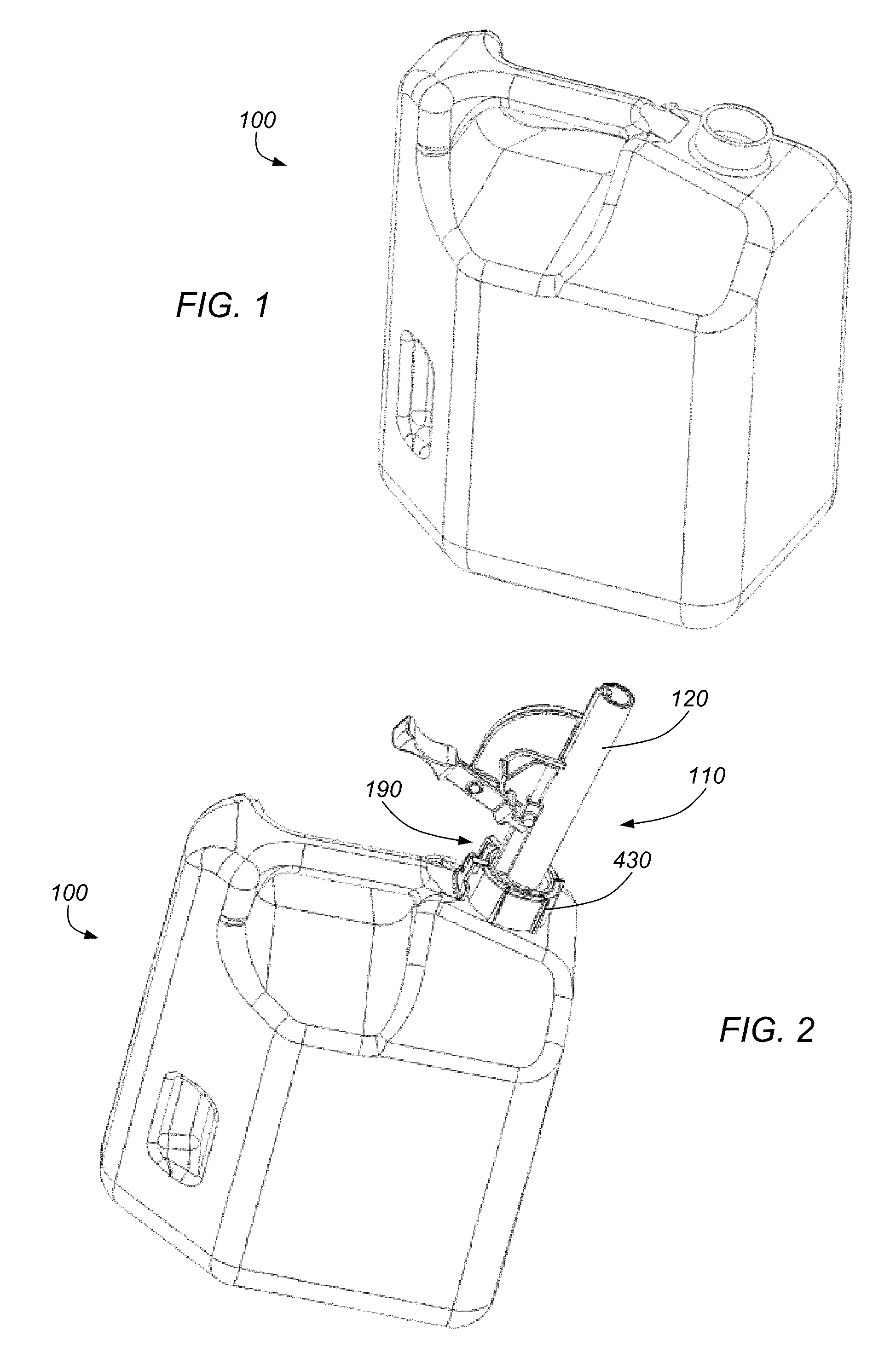
PRIORITY CLAIM[0001]This application claims priority to U.S. Provisional Patent Application No. 61 / 994,361 entitled “POURABLE SPOUT WITH CHILD PROOF MECHANISM” filed on May 16, 2014, and U.S. Provisional Patent Application No. 62 / 039,245 entitled “POURABLE SPOUT WITH CHILD PROOF MECHANISM” filed on Aug. 19, 2014, all of which are incorporated by reference herein.BACKGROUND OF THE INVENTION[0002]1. Field of the Invention[0003]The present disclosure generally relates to pouring spouts. More particularly, the disclosure generally relates to a method and system for pouring liquid through a spout assembly couplable to a container.[0004]2. Description of the Relevant Art[0005]When transferring fluids from a container, typically it is necessary to attach a pouring spout to the container to prevent unwanted spillage. Such transfer methods are commonly used to deliver fluids (e.g., motor oil, antifreeze, transmission fluid, and gasoline) to a vehicle. FIG. 1 depicts a perspective view of a r...

Claims


Application Information

Patent Timeline
Patent Type & Authority Applications(United States)
IPC IPC(8): B65D47/06
CPCB65D47/06B65D47/248B65D25/48
Inventor WILKINSON, WILLIAM R.WILKINSON, ZACHARY A.
Owner MINERVA MFG
Learn More