Apparatus for performing binding processing on sheets and post-processing apparatus provided with the same
a technology for post-processing apparatus and sheets, which is applied in the direction of electrographic process, instruments, transportation and packaging, etc., to achieve the effect of convenient separation, desired binding strength and easy separation
- Summary
- Abstract
- Description
- Claims
- Application Information
AI Technical Summary
Benefits of technology
Problems solved by technology
Method used
Image
Examples
embodiment 1
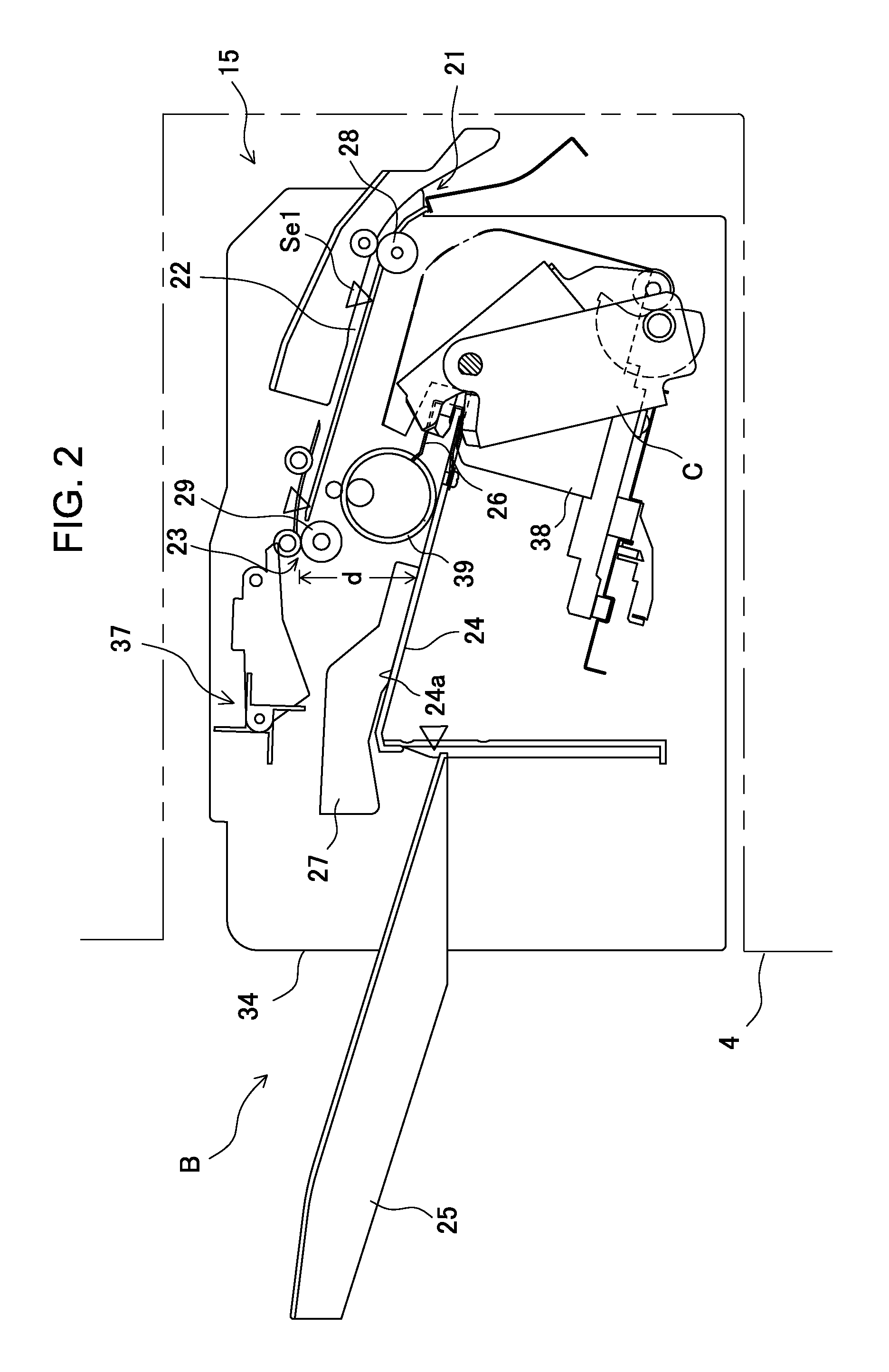
[0080]Embodiment 1 will be described according to FIGS. 6A to 6D. The post-processing apparatus B as described previously is provided with the positioning reference (Sp) to position sheets in a predetermined processing position (binding position) P in collecting the sheets on the processing tray 24, and the binding processing section 49 is disposed to perform the binding processing on the sheets positioned in the reference.
[0081]In Embodiment 1 as shown in the figure, as the positioning reference Sp, it is configured to enable the sheet regulating position of the sheet end regulating member 26 to be selected from between reference 1 (Sp1) and reference 2 (Sp2). Therefore, as shown in FIG. 6D, the sheet end regulating member (striking stopper) 26 is supported on the bottom of the processing tray 24 to be able to shift (slidably) in the sheet carry-in direction (vertical direction as viewed in the figure). The sheet end regulating member 26 is configured to be able to shift a sheet re...
embodiment 2
[0086]Embodiment 2 as shown in FIGS. 7A to 7D will be described. As the regulating section to position sheets on the processing tray 24, the Embodiment shown in the figure shows the case of “enabling the pair of right and left side edge regulating members 27 to shift to positions between the first reference Cp1 and the second reference Cp1”.
[0087]Described is the case of positioning sheets in a processing position in the center reference as shown in the figure. The pair of right and left side edge regulating members 27 are supported on the processing tray 24 to be able to shift in the width direction. In the member 27 shown in the figure, each of side edge regulating members 27a, 27b is fitted slidably into a guide groove (not shown) disposed on the bottom of the processing tray 24. In each of the side edge regulating members 27a, 27b are disposed the alignment motor M1 (in the members shown in the figure, a pair of right and left drive motors), and the transmission mechanism 56 (ra...
embodiment 3
[0091]The Embodiment as shown in FIGS. 8A to 8E will be described. In the processing tray 24 are disposed the sheet end regulating member 26 that regulates the end edge of the sheet, and the side edge regulating member 27 that regulates sheet side edges, and each of the regulating members 26, 27 is fixed to a predetermined position without making a position adjustment to the reference position of regulating operation.
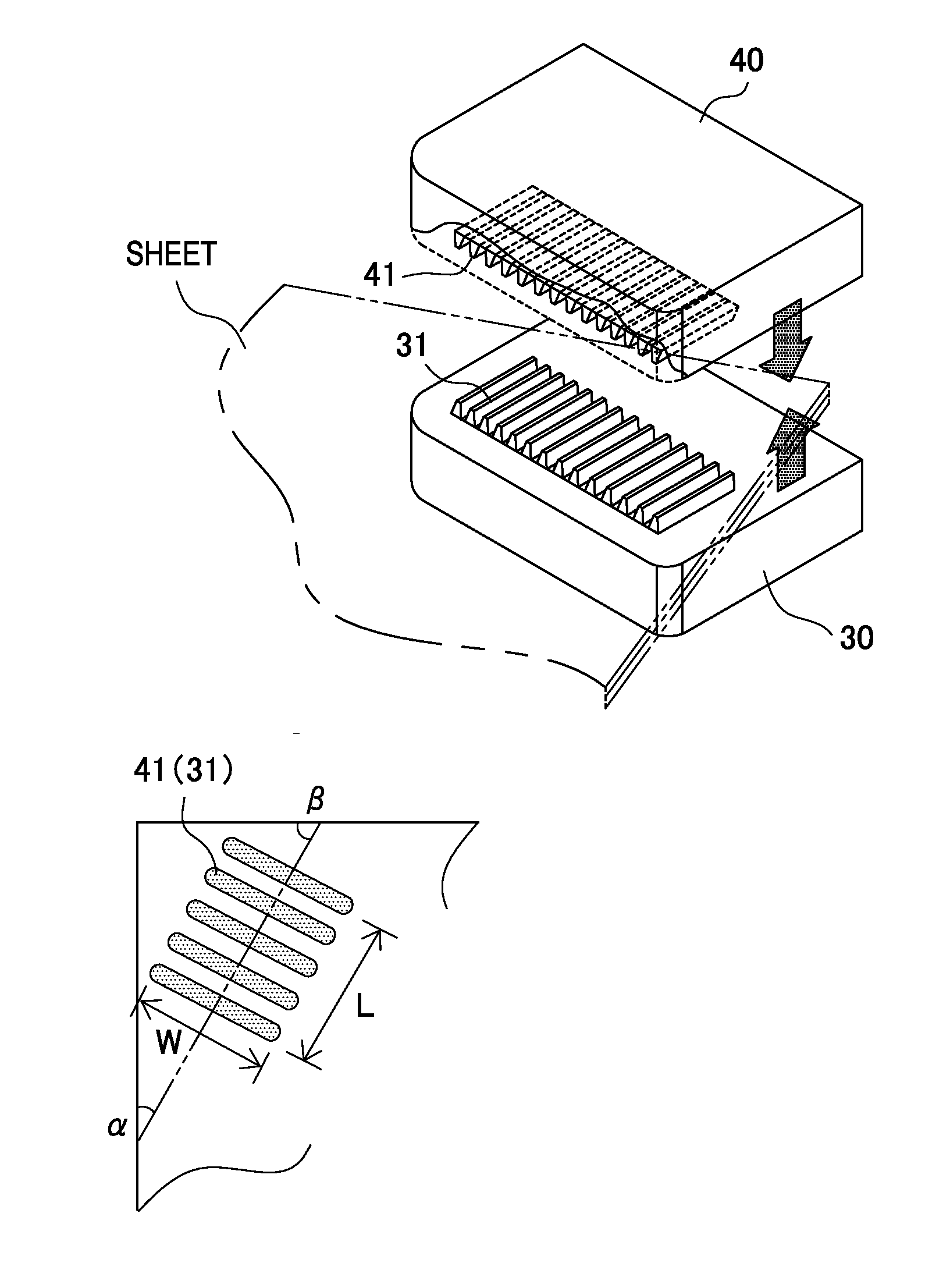
[0092]Then, the binding processing section 49 is attached to the apparatus frame (not shown) to be able to shift to positions, and as shown in FIG. 8E, is comprised of a shift motor SM2 and transmission mechanism 57 (rack-and-pinion mechanism, belt-and-pulley mechanism, or the like), and in a state in which the binding position is the first reference Dp1 (FIG. 8A) or the second reference Dp2 (FIG. 8B), the pressurizing surfaces 31, 41 are configured to be able to shift to positions with respect to the sheets on the processing tray.
[0093]As the set positions of the first...
PUM
| Property | Measurement | Unit |
|---|---|---|
| Width | aaaaa | aaaaa |
Abstract
Description
Claims
Application Information
 - R&D
- Intellectual Property
- Life Sciences
- Materials
- Tech Scout
- Unparalleled Data Quality
- Higher Quality Content
- 60% Fewer Hallucinations
Browse by: Latest US Patents, China's latest patents, Technical Efficacy Thesaurus, Application Domain, Technology Topic, Popular Technical Reports.
© 2025 PatSnap. All rights reserved.Legal|Privacy policy|Modern Slavery Act Transparency Statement|Sitemap|About US| Contact US: help@patsnap.com


