Eureka AIR delivers breakthrough ideas for toughest innovation challenges, trusted by R&D personnel around the world.

Automatic stop/restart control system for an internal combustion engine and variable valve actuating apparatus

a control system and internal combustion engine technology, applied in the direction of electric control, engine starters, machines/engines, etc., can solve the problems of inability to effectively use the expansion energy of the combustion gas, the inability to acquire sufficient combustion torque (rotational force) at the restart, and the inability to start the starter-less engine. the effect of reducing the number of revolutions, increasing the ratio of the starter-less start, and effectively using the combustion torqu

Inactive Publication Date: 2015-12-24
HITACHI AUTOMOTIVE SYST LTD
View PDF7 Cites 14 Cited by
  • Summary
  • Abstract
  • Description
  • Claims
  • Application Information

AI Technical Summary

Benefits of technology

[0015]It is an object of the present invention to provide an automatic stop / restart control system for an internal combustion engine, which is capable of reducing the number of revolutions (rotational speed) permitting the starter-less start by effectively using the combustion torque of the combustion gas acquired by the combustion of the fuel when the restart request is generated after the stop of the fuel injection so as to restart the supply of the fuel in response to the restart request, thereby increasing the ratio of the starter-less start, and to provide a variable valve actuating apparatus to be used in this system.
[0016]Another object of the present invention is to provide an automatic stop / restart control system for an internal combustion engine, which is capable of suppressing the generation of the excessive peak combustion pressure, which generates the rotational fluctuation and thus makes the occupants feel the sense of discomfort, when the restart request is generated after the stop of the fuel injection so as to restart the supply of the fuel, thereby enabling a smooth starter-less start, and to provide a variable valve actuating apparatus to be used in this system.
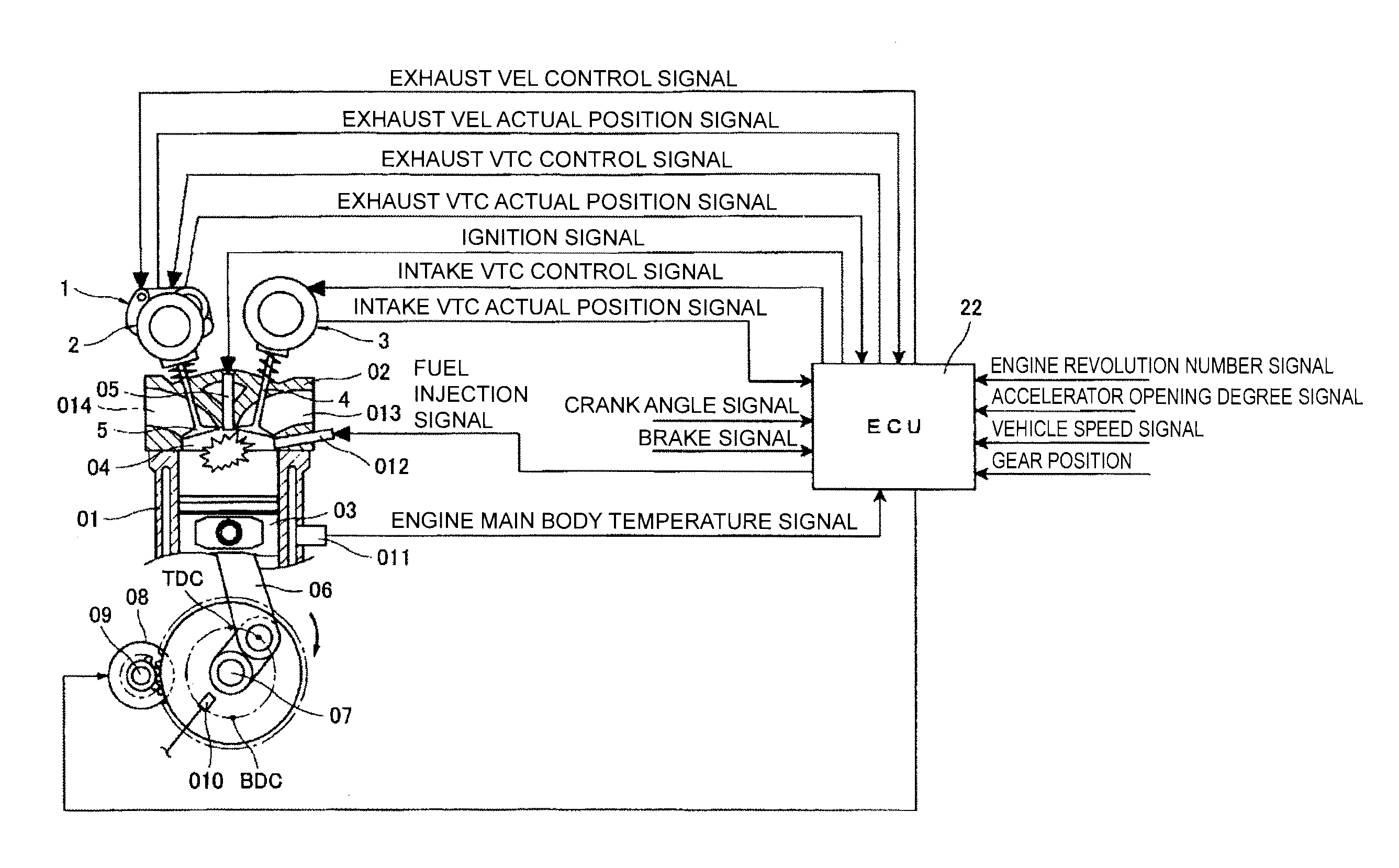
[0017]According to one aspect of the present invention, an open timing of exhaust valves is retarded to the vicinity of a bottom dead center on an expansion stroke end side in a course of a decrease in a rotational speed of an internal combustion engine after stop of fuel injection, thereby effectively using a combustion torque of a combustion gas of a fuel caused by the fuel injection upon restart.
[0018]According to one aspect of the present invention, the open timing of the exhaust valves is retarded to the vicinity of the bottom dead center on the expansion stroke end side in the course of the decrease in the rotational speed of the internal combustion engine after the stop of the fuel injection, thereby effectively using the combustion torque of the combustion gas of the fuel caused by the fuel injection upon the restart, and a close timing of intake valves is changed to the vicinity of a bottom dead center on an intake stroke end side, thereby suppressing a discharge of fresh air backward to the intake system side upon the transition to a compression stroke.

Problems solved by technology

Thus, expansion energy of the combustion gas cannot be effectively used in the expansion stroke, and thus a sufficient combustion torque (rotational force) is hard to be acquired at the restart.
When a sufficient combustion torque cannot be acquired at the restart in the area where the rotational speed is low, the starter-less start becomes impossible, and the start needs to be changed to the start using the starter.
Thus, the method described in Japanese Patent Application Laid-open No. 2010-242621 (Patent Document) can carry out the starter-less start only down to a relatively high lower limit rotational speed, and there is such a problem in that the ratio of the starter-less start cannot be sufficiently increased.
On this occasion, it is conceivable to excessively increase the charging efficiency, or to set the air-fuel ratio to be rich in order to secure the combustion torque at the starter-less start.
In this case, however, a peak combustion pressure excessively increases, and a rotational fluctuation of the engine at the starter-less start increases, which is suspected to make occupants feel sense of discomfort.

Method used


Image

  • Automatic stop/restart control system for an internal combustion engine and variable valve actuating apparatus
  • Automatic stop/restart control system for an internal combustion engine and variable valve actuating apparatus
  • Automatic stop/restart control system for an internal combustion engine and variable valve actuating apparatus

Examples


first embodiment

[0086]Referring to FIGS. 8A to 11, a detailed description is now given of a first embodiment of the present invention in an internal combustion engine including the variable valve actuating apparatus as described above. On this occasion, in the embodiment described below, the open timing (EVO1) of the exhaust valves 5 and the close timing (IVC1) of the intake valves 4 upon the restart are both default positions, and are the mechanically stable positions.

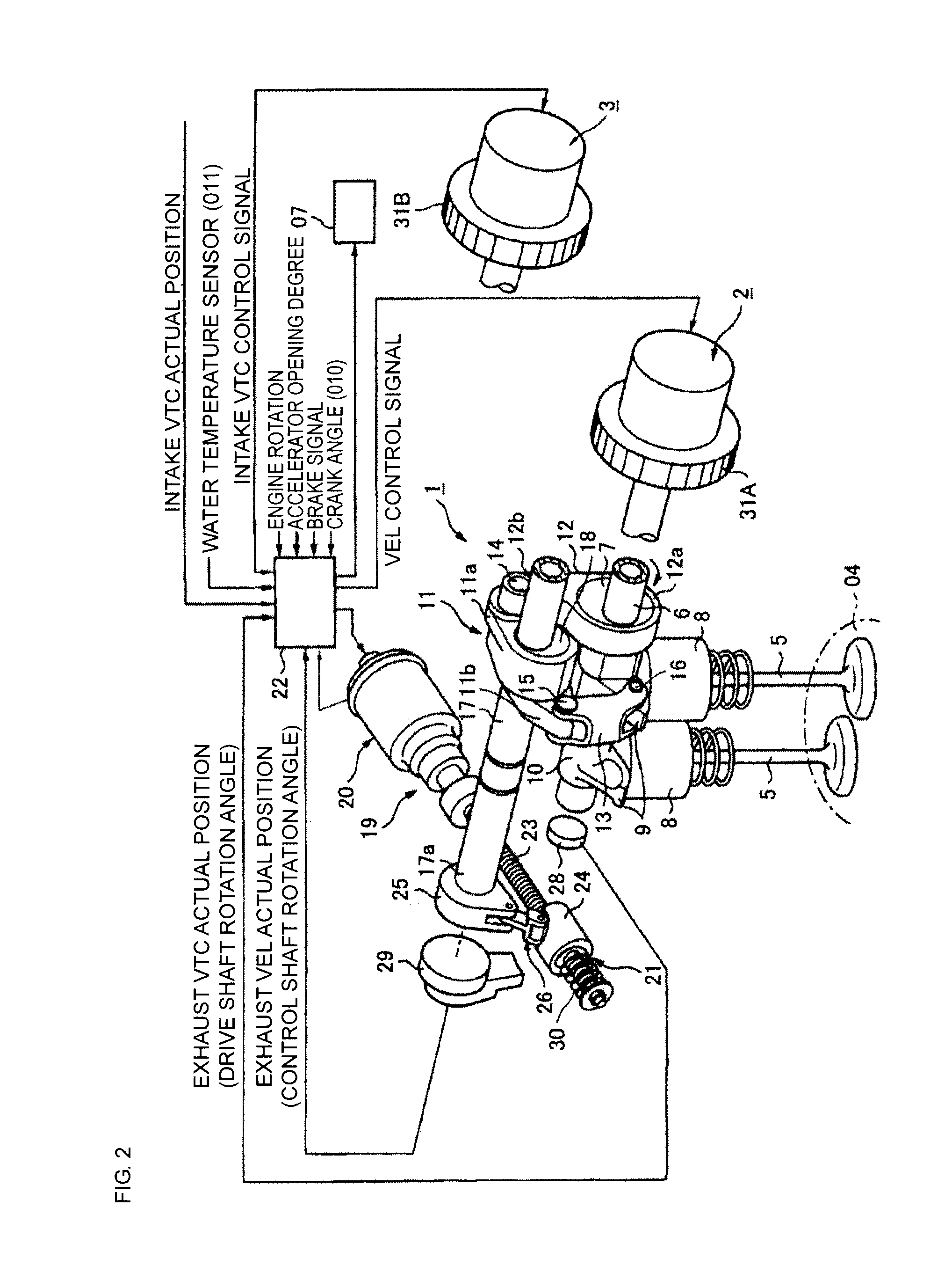
[0087]FIGS. 8A and 8B represent behaviors of the exhaust valves 5 and the intake valves 4 while the automatic stop state (upon the fuel injection stop) transitions to the restart state according to this embodiment. On this occasion, the exhaust valves 5 are controlled by the exhaust VEL 1, and the intake valves 4 are controlled by the intake VTC 3.

[0088]A left diagram of FIG. 8A illustrates an example of the open / close states of the exhaust valves 5 and the intake valves 4 in a low rotation travel state before a transition to the aut...

second embodiment

[0150]Referring to FIGS. 12A and 12B, a description is now given of a second embodiment of the present invention. In the first embodiment, when the restart request is generated at the number of revolutions equal to or less than the first predetermined number of revolutions Nk1, the open timing of the exhaust valves 5 and the close timing of the intake valves 4 are changed. The second embodiment is different in such a point that the control signals for changing the open timing of the exhaust valves 5 and the close timing of the intake valves 4 are output without waiting for the restart request at the time point Ta at which the number of revolutions N has decreased to be equal to or less than a fourth predetermined number of revolutions Nk4. It should be noted that the same reference numerals in a flowchart illustrated in FIG. 12B as those of the control steps in the flowchart illustrated in FIG. 11 denote the same processing, and a brief description is thus given thereof.

[0151]As ill...

third embodiment

[0160]With reference to FIGS. 13A and 13B, a description is now given of a third embodiment of the present invention. In the first embodiment, the exhaust VEL 1 is used for controlling the open timing of the exhaust valves 5, but the third embodiment is different in such a point that the exhaust VTC 2 is used in place of the exhaust VEL 1. Thus, the valve lift of the exhaust valves 5 is not controlled, and the valve timing (phase) is controlled as by the intake VTC 3.

[0161]The exhaust VTC 2 and the intake VTC 3 according to this embodiment include practically the same configuration, and both the VTCs 2 and 3 are different from the intake VTC according to the first and second embodiments, and have the most retarded positions as the default positions. In other words, the coil springs 55 and 56 for biasing the vanes 32b of the vane member 32 bias the vanes 32b to the retarded side, and the vanes 32b are set to the most retarded phase when the hydraulic pressure is not supplied. Then, t...


PUM


Abstract

An automatic stop/restart control system for an internal combustion engine comprising: an engine stop device configured to stop fuel injection from a fuel injection valve in response to generation of an engine stop request during an operation of an internal combustion engine; and a restart device configured to restart the fuel injection from the fuel injection valve and opening an exhaust valve in a vicinity of a bottom dead center on an expansion stroke end side in response to generation of a restart request by a driver in a course of a decrease in number of revolutions of the internal combustion engine during stop of the fuel injection by the engine stop device.

Description

TECHNICAL FIELD[0001]The present invention relates to an automatic stop / restart control system for an internal combustion engine, which has a function of restarting an internal combustion engine in a course of a decrease in a rotational speed of the internal combustion engine as a result of automatic stop control, and to a variable valve actuating apparatus to be used in this system.BACKGROUND ART[0002]In recent years, an increasing number of vehicles have an automatic stop / restart control system (so-called start-stop control system) for an internal combustion engine installed thereon in order to improve fuel economy, reduce exhaust emission, and the like. The related-art general start-stop control system stops, when a driver stops a vehicle, fuel injection so as to automatically stop an internal combustion engine, and then, when the driver carries out an operation (brake release operation or accelerator depression operation) to start the vehicle, automatically supplies a current to...

Claims


Application Information

Patent Timeline
Patent Type & Authority Applications(United States)
IPC IPC(8): F02N11/08F02D13/02
CPCF02N11/0803F02D2013/0292F02D13/0203F01L1/3442F01L13/0026F01L2001/0537F01L2001/3443F01L2001/34469F01L2001/34483F01L2013/0073F01L2250/02F01L2820/032F02B2075/125F02D13/0211F02D13/0219F02D13/08F02D41/0002F02D41/042F02D41/065F02D2041/001F02D2200/101F02N11/0844F02N19/004F02N2200/022Y02T10/12Y02T10/40
Inventor NAKAMURA, MAKOTO
Owner HITACHI AUTOMOTIVE SYST LTD
Why Eureka
Eureka Blog
Learn More