
Air-fuel ratio control apparatus of internal combustion engine

a technology of air-fuel ratio and control apparatus, which is applied in the direction of electric control, speed sensing governor, machines/engines, etc., can solve the problems of increasing the difficulty of carrying out the stop of fuel supply, so as to achieve the reduction of the effect of reducing the number of revolutions of fuel cu

Inactive Publication Date: 2006-12-05
TOYOTA JIDOSHA KK
View PDF13 Cites 8 Cited by
  • Summary
  • Abstract
  • Description
  • Claims
  • Application Information

AI Technical Summary

Benefits of technology

[0004]It is an object of the present invention to provide an air-fuel ratio control apparatus of an internal combustion engine in which sufficient amount of oxygen to suppress the catalyst exhaust smell can reliably be occluded in an exhaust gas purifying catalyst until the internal combustion engine is decelerated or stopped after the fuel increasing operation of the internal combustion engine.
[0005]To solve the above problem, the present invention provides an air-fuel ratio control apparatus of an internal combustion engine in which an exhaust gas purifying catalyst is disposed in an exhaust passage, comprising: fuel cut means which stops fuel supply to the internal combustion engine when it is determined that a number of revolutions of the internal combustion engine is higher than a fuel cut number of revolutions at the time of deceleration of the internal combustion engine; and changing means of the fuel cut number of revolutions for changing the fuel cut number of revolutions according to a physical amount which correlates with an amount of oxygen discharged from the exhaust gas purifying catalyst during a fuel increasing operation of the internal combustion engine such that as the amount of oxygen is greater, the fuel cut number of revolutions is reduced.
[0006]Since exhaust gas of the rich air-fuel ratio including CO and HC flows into the exhaust gas purifying catalyst during the fuel increasing operation, oxygen is discharged from the exhaust gas purifying catalyst. If the fuel supply to the internal combustion engine is stopped by the fuel cut means, the concentration of oxygen in the exhaust gas becomes substantially equal to the concentration of oxygen in the air, so that the oxygen is occluded in the exhaust gas purifying catalyst. According to the air-fuel ratio control apparatus of the internal combustion engine of the present invention, since the changing means of the fuel cut number of revolutions reduces the fuel cut number of revolutions as the amount of discharged oxygen during the fuel increasing operation is increased, the stop of the fuel supply by the fuel cut means can be easily carried out. Thus, when the internal combustion engine is decelerated, more oxygen can be occluded in the exhaust gas purifying catalyst. Therefore, sufficient amount of oxygen to suppress the catalyst exhaust odor can reliably be occluded in the exhaust gas purifying catalyst until the internal combustion engine is decelerated or stopped after the fuel increasing operation.

Problems solved by technology

When the total intake air amount is small, i.e., when the amount of oxygen discharged from the exhaust gas purifying catalyst is small, the fuel cut number of revolutions is increased and it becomes difficult to carry out the stop of the fuel supply, so that the environment around the exhaust gas purifying catalyst is hard to be an oxygen excessive state.

Method used


Image

  • Air-fuel ratio control apparatus of internal combustion engine
  • Air-fuel ratio control apparatus of internal combustion engine
  • Air-fuel ratio control apparatus of internal combustion engine

Examples


first embodiment

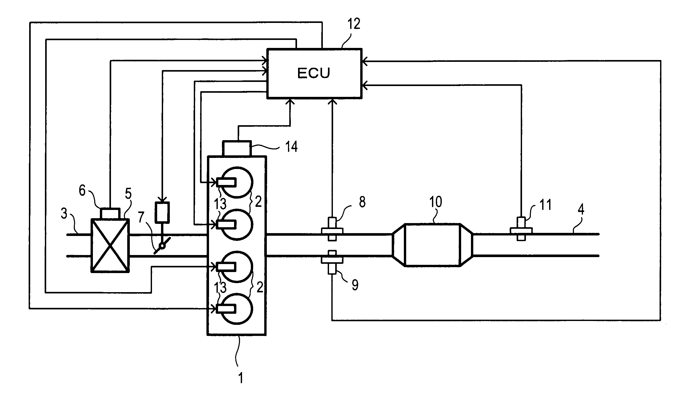
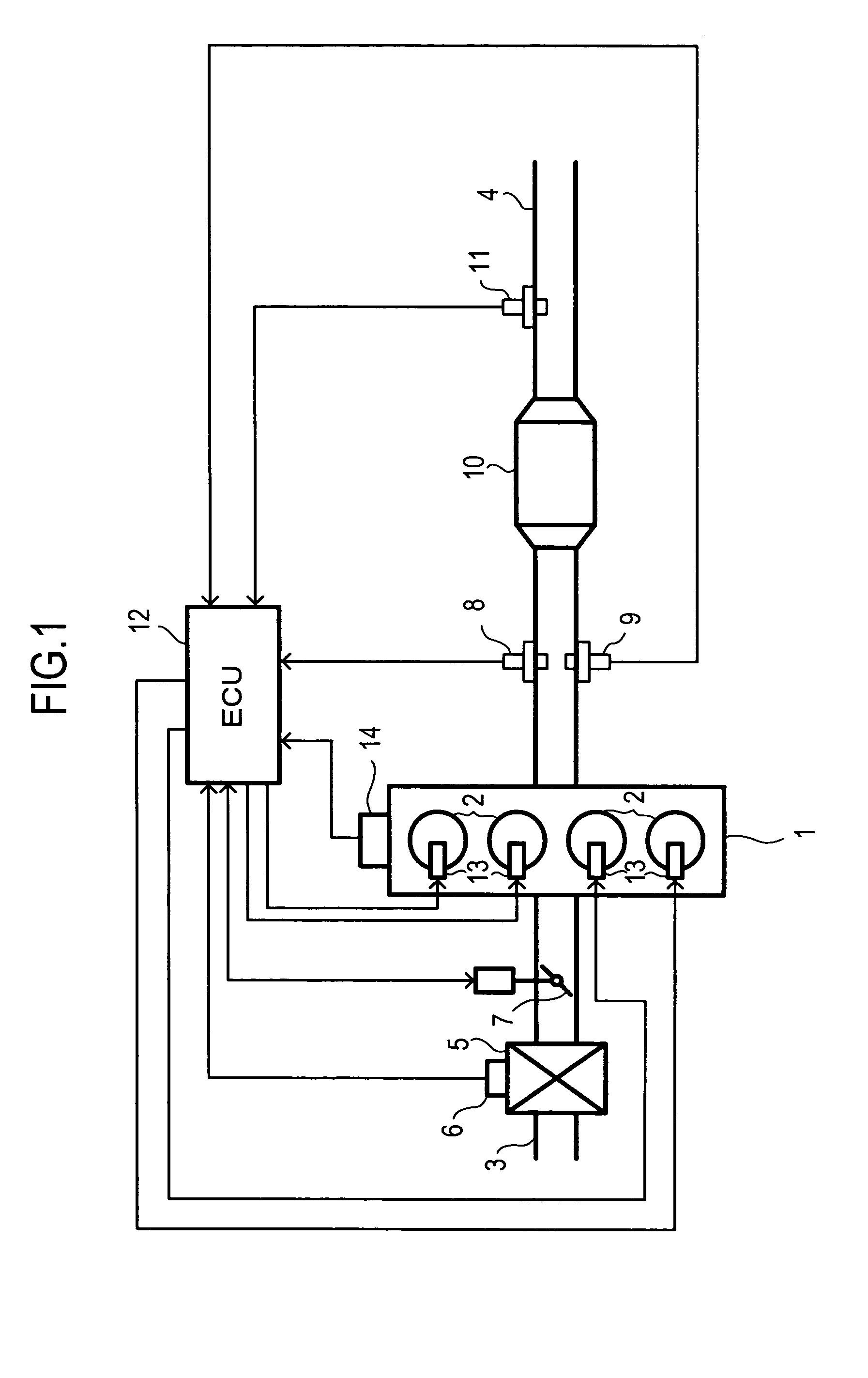
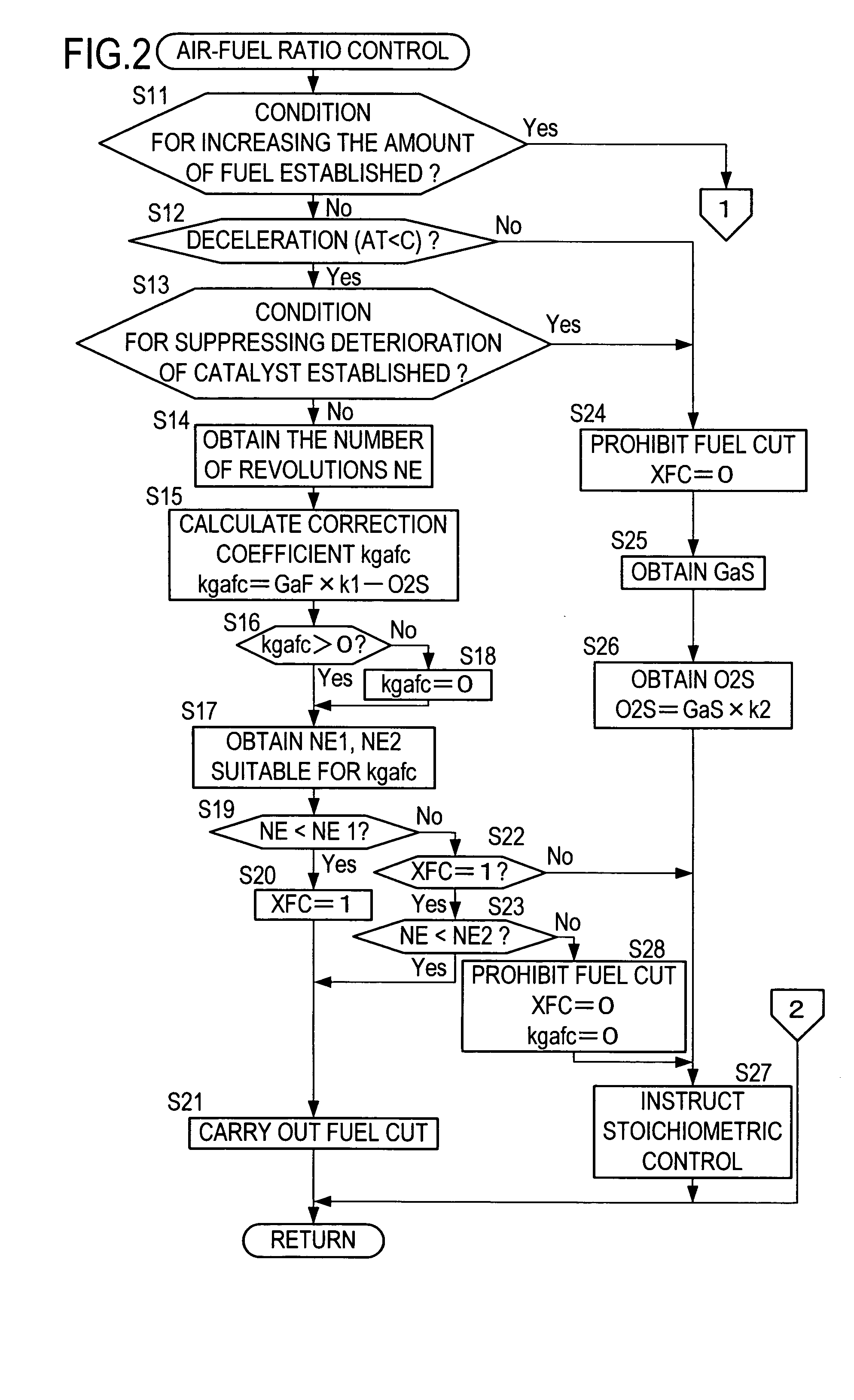
[0023]FIGS. 2 and 3 are flowcharts showing a control routine of the air-fuel ratio which is carried out by the ECU 12 to control the air-fuel ratio of the internal combustion engine 1. The control routine of the air-fuel ratio shown in FIGS. 2 and 3 is repeatedly carried out at predetermined cycle during the operation of the internal combustion engine 1.

[0024]In the air-fuel ratio control routine shown in FIG. 2, the ECU 12 first determines in step S11 whether a fuel amount increasing condition for increasing the amount of fuel to be supplied to the internal combustion engine 1 is established. The fuel amount increasing condition is established, for example, when the increase of the output of the internal combustion engine 1 is required. If it is determined that the fuel amount increasing condition is not established, the procedure is proceeded to step S12, where the ECU 12 determines whether the internal combustion engine 1 is in a decelerated state. If the opening of the throttle ...

second embodiment

[0030]FIGS. 5 and 6 are flowcharts showing the air-fuel ratio control routine which is carried out by the ECU 12. The air-fuel ratio control routine in FIGS. 5 and 6 is repeatedly carried out at predetermined intervals during operation of the internal combustion engine 1. In FIGS. 5 and 6, the same processing is designated with the same step numbers as that of the FIGS. 2 and 3, and explanation thereof will be omitted.

[0031]In the air-fuel ratio control routine shown in FIG. 5, the ECU 12 first obtains a maximum oxygen occluding amount Cmax of the catalyst 10 in step S51. The Cmax is calculated by a Cmax calculation routine which is different from the air-fuel ratio control routine, and the Cmax is stored in the RAM of the ECU 12. The Cmax can be obtained by the following method for example. When the internal combustion engine 1 is operated in a substantially steady state in a partial load region, rich control for bringing the air-fuel ratio of the internal combustion engine 1 to ri...

third embodiment

[0035]FIGS. 8 and 9 are flowcharts showing the air-fuel ratio control routine carried out by the ECU 12. The air-fuel ratio control routine in FIGS. 8 and 9 is repeatedly carried out at predetermined intervals during operation of the internal combustion engine 1. In FIGS. 8 and 9, the same processing is designated with the same step numbers as that of the FIGS. 5 and 6, and explanation thereof will be omitted.

[0036]In the air-fuel ratio control routine in FIG. 8, the same processing as that of the control routine shown in FIG. 5 is carried out until the number of revolutions NE of the internal combustion engine 1 is obtained (step S14). In next step S61, the ECU 12 calculates the correction coefficient kgafc. The correction coefficient kgafc can be calculated by subtracting O2S and an amount O2FC of oxygen supplied to the catalyst 10 in a period during which the fuel cut is carried out. The amount O2FC can be obtained in later-described step S63, from a value obtained by multiplying...


PUM


Abstract

An air-fuel ratio control apparatus of an internal combustion engine in which an exhaust gas purifying catalyst is disposed in an exhaust passage, comprises: fuel cut means which stops fuel supply to the internal combustion engine when it is determined that a number of revolutions of the internal combustion engine is higher than a fuel cut number of revolutions at the time of deceleration of the internal combustion engine; and changing means of the fuel cut number of revolutions for changing the fuel cut number of revolutions according to a physical amount which correlates with an amount of oxygen discharged from the exhaust gas purifying catalyst during the fuel increasing operation of the internal combustion engine such that as the amount of oxygen is greater, the fuel cut number of revolutions is reduced.

Description

BACKGROUND OF THE INVENTION[0001]The present invention relates to an air-fuel ratio control apparatus of an internal combustion engine.[0002]There is known an air-fuel ratio control apparatus of an internal combustion engine in which when fuel of the internal combustion engine is increased and output of an oxygen concentration sensor provided downstream from a catalytic converter shows rich, an air-fuel ratio is controlled to a lean side during a predetermined time and then, the air-fuel ratio is returned to a theoretical air-fuel ratio (see Japanese Patent Application Laid-open (JP-A) No. 63-117139). As other arts related to the present invention, there are patent documents JP-A Nos. 63-134835, 6-307271, and 59-173533.[0003]When CO or HC exists in exhaust gas, the exhaust gas purifying catalyst oxidizes CO or HC using occluded oxygen or oxygen in the exhaust gas. When oxide component such as NOx is included in the exhaust gas, the exhaust gas purifying catalyst reduces the oxide co...

Claims


Application Information

Patent Timeline
Patent Type & Authority Patents(United States)
IPC IPC(8): F01N3/00F01N3/24F01N3/01F02D31/00F02D41/04F02D41/12F02D41/14
CPCF01N3/01F02D31/009F02D41/123F02D41/1441F01N2430/02Y02T10/20Y02T10/12
Inventor YOSHIOKA, MAMORU
Owner TOYOTA JIDOSHA KK
Learn More