

Three-phase alternating current electric motor provided with structure reducing torque ripple
a technology of alternating current and structure, which is applied in the direction of rotating magnets, synchronous motors, windings, etc., can solve the problems of increasing production manhours, vibration and noise at the apparatus, and small effect, so as to reduce the number of production processes and reduce the effect of torque rippl
- Summary
- Abstract
- Description
- Claims
- Application Information
AI Technical Summary
Benefits of technology
Problems solved by technology
Method used
Image

Examples
example 1
CONVENTIONAL EXAMPLE 1
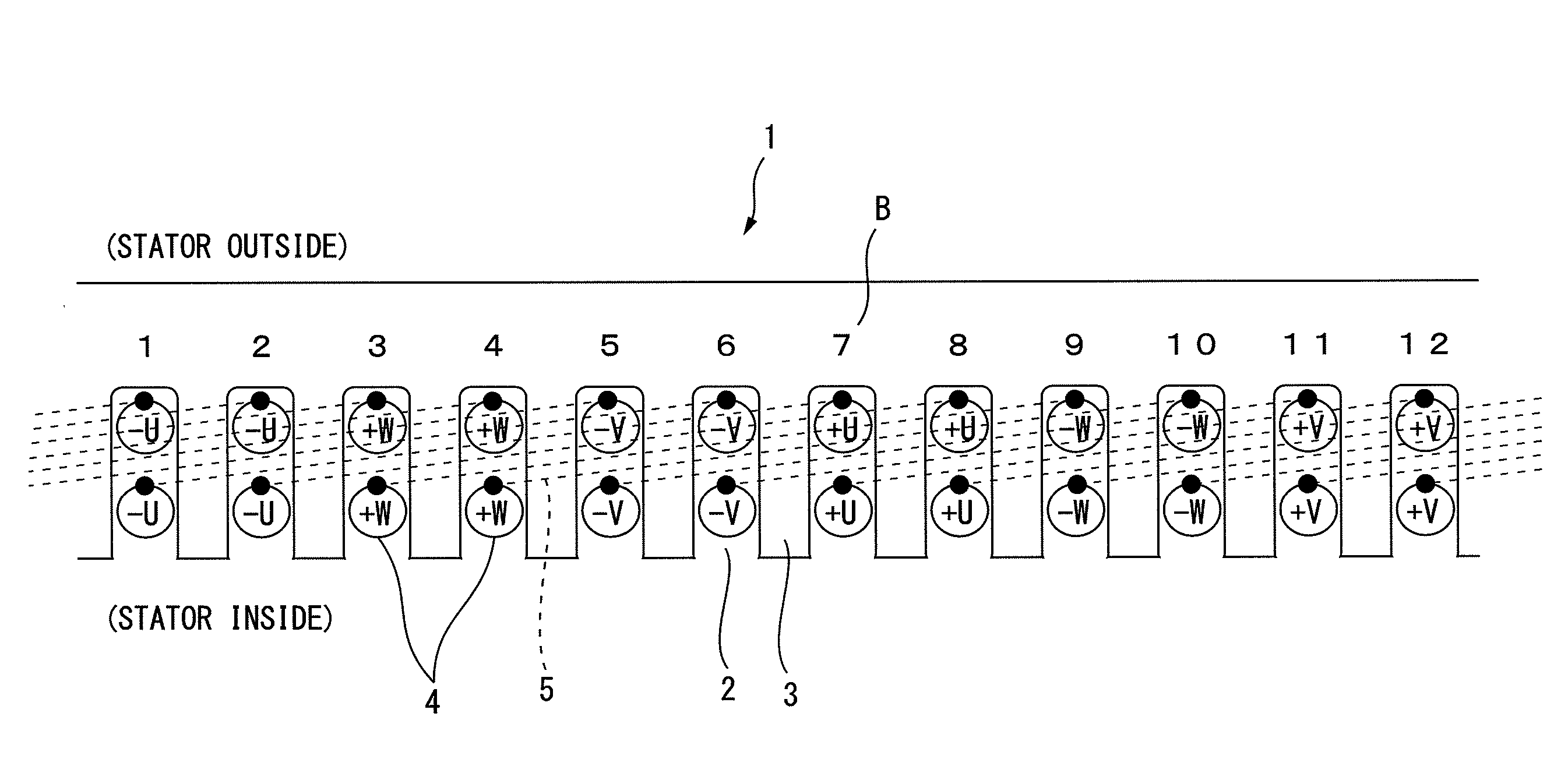
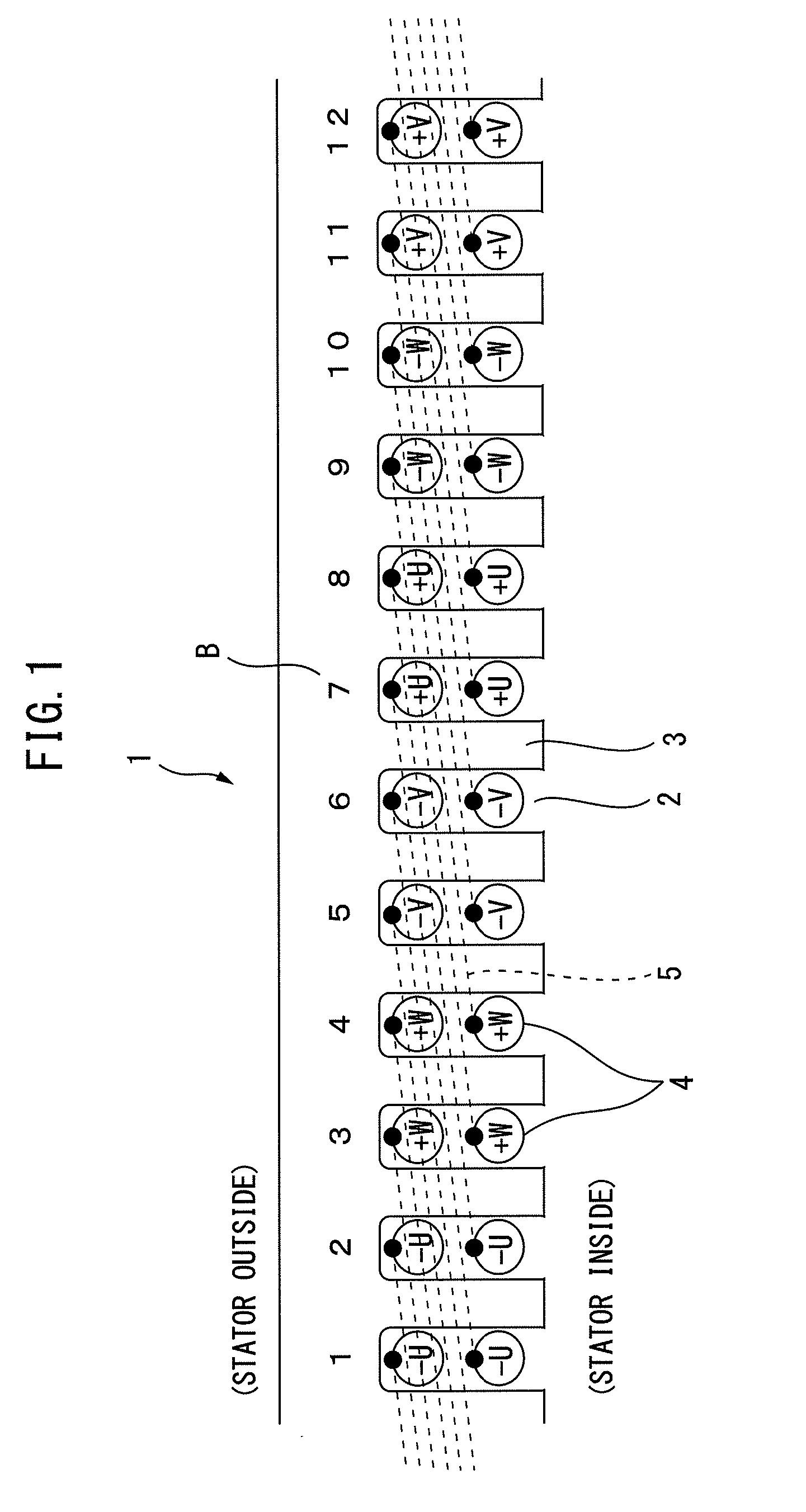
[0029]FIG. 1 illustrates one example of an integral slot type stator 1 of a conventional alternating current electric motor (Conventional Example 1) and illustrates a 6-pole 36-slot winding layout. The integral slot configuration is the case where (number of slots)÷(number of poles) becomes a whole number (in the example which is illustrated in FIG. 1, 36÷6=6). The stator 1 is originally a cylindrical shape, but to facilitate the explanation here, the cylindrical shape stator 1 is illustrated as a developed cross-section which is opened up linearly. Further, in the subsequent conventional examples and examples of the present invention as well, in the explanation of the layout of the windings 4 at the stator 1, this developed cross-sectional view will be used to explain the layout of the stator 1 and windings 4. Note that, FIG. 1 illustrates the cross-section of part of the developed stator 1 (12 slots worth).
[0030]Further, the alternating current is a three-pha...
example 2
CONVENTIONAL EXAMPLE 2
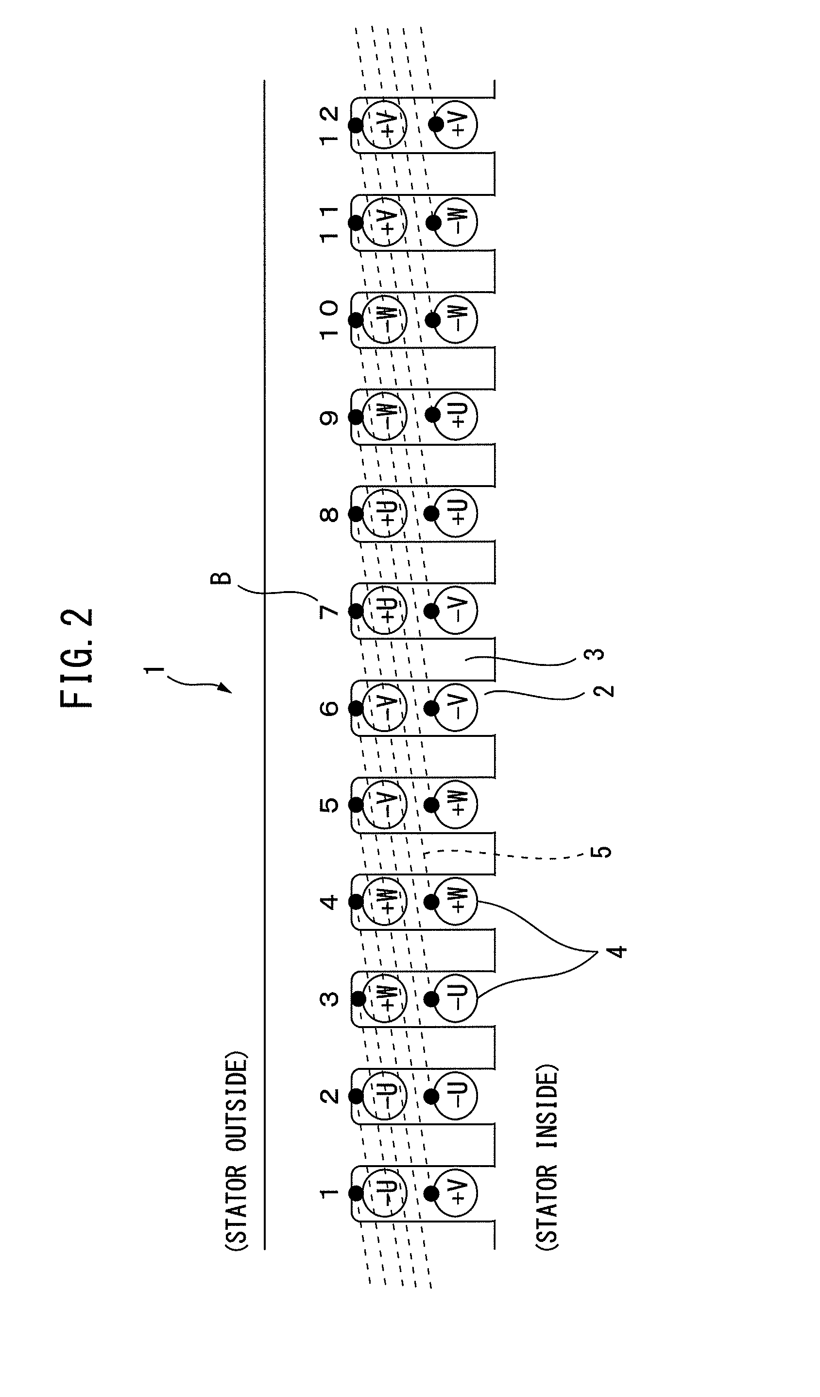
[0032]FIG. 2 illustrates another example of an integral slot type stator 1 of a conventional alternating current electric motor (Conventional Example 2) and illustrates a 6-pole 36-slot winding layout. FIG. 2 also illustrates part of the stator 1 (12 slots worth). The winding layout of Conventional Example 2 differs from the winding layout of Conventional Example 1 in the point that the winding of the second layer of each phase of the two-layer winding is offset by 1 slot to the right side. For this reason, the other winding of the winding 4 at the time of lap winding, as illustrated by the line illustrated by the notation 5, becomes a position separated by (180 degrees×⅚) in terms of electrical angle. In the Conventional Example which is illustrated in FIG. 2, there is a 5 slot coil pitch, so the coil pitch becomes 150 degrees converted to electrical angle.
[0033]Short Pitch Winding of Distributed Winding
[0034]In Conventional Example 2 which is illustrated in F...
example 3
CONVENTIONAL EXAMPLE 3
[0035]FIG. 3 illustrates still another example of a fractional slot type stator 6 of a conventional alternating current electric motor (Conventional Example 3) and illustrates a known 4-pole 15-slot winding layout. Two phases are arranged in one slot (two-layer winding). The number of slots occupied by the different phases becomes somewhat uneven. Conventional Example 3 is the case where (number of slots)÷(number of poles)÷(number of phases) becomes 15÷4÷3= 5 / 4 or an irreducible fraction with a denominator of 4 or more. Further, the other winding at the time of lap winding is at a position which is offset by several slots between the first layer and the second layer. Two slots are positioned separated from each other by about 180 degrees in terms of electrical angle.
[0036]In Conventional Example 3, there is a 4 slot coil pitch. The center angle between the slots is 192 degrees converted to electrical angle thereby giving a long pitch winding. Note that, the met...
PUM
 Abstract
Description
Claims
Application Information