
Method for supplying electrical power to a DC motor which can be commutated electronically via a semiconductor power output stage

a technology of electrical power supply and dc motor, which is applied in the direction of electronic commutators, motor/generator/converter stoppers, dynamo-electric converter control, etc., can solve the problems of low efficiency of motors, complex sensor technologies, etc., and achieve low switching and computing expenses, increase power density, and reduce torque ripple

Inactive Publication Date: 2010-08-17
ROBERT BOSCH GMBH
View PDF13 Cites 3 Cited by
  • Summary
  • Abstract
  • Description
  • Claims
  • Application Information

AI Technical Summary

Benefits of technology

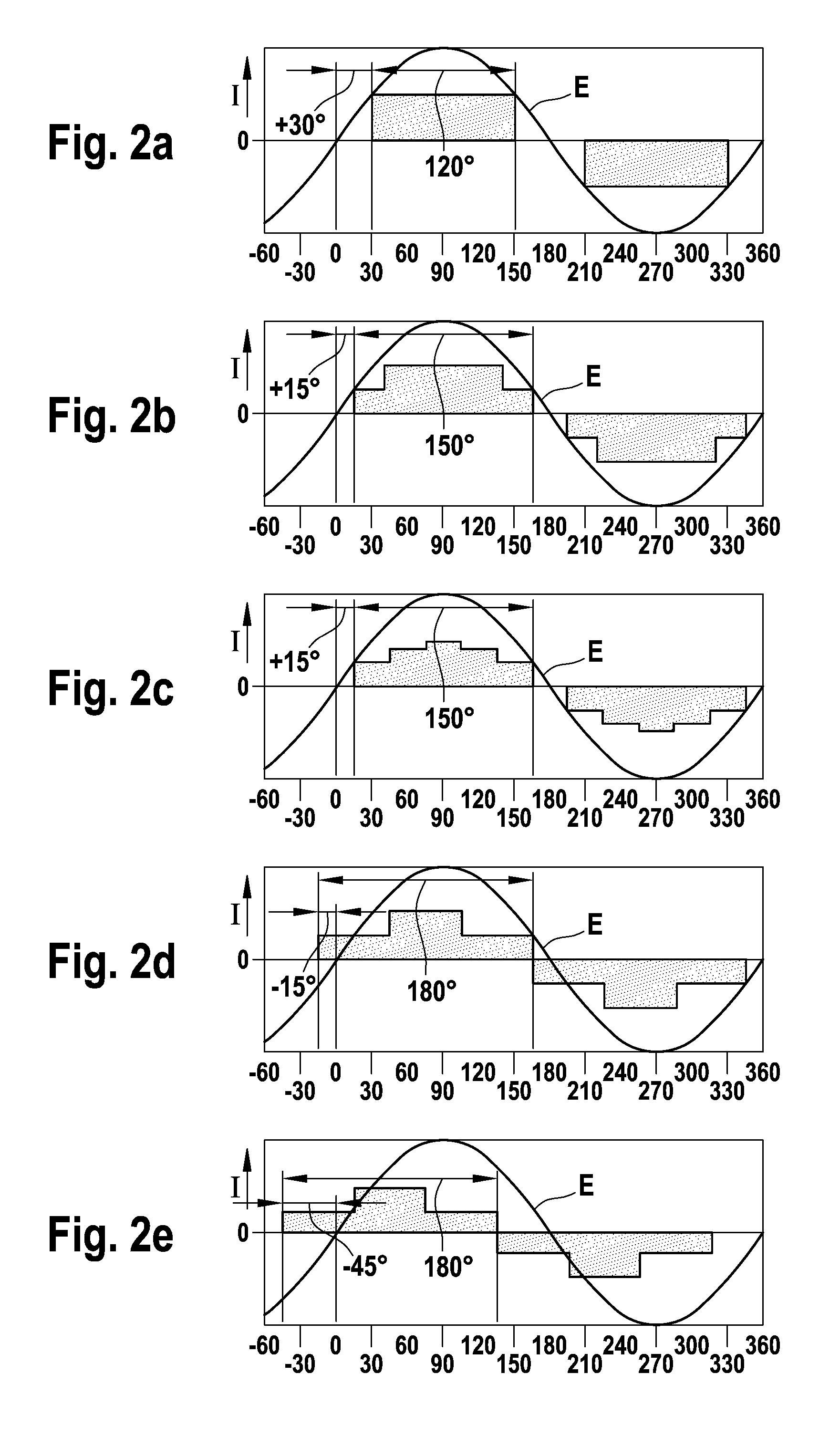
[0002]The invention is based on the objective of disclosing a method for supplying electrical power to a DC motor which can be commutated electronically via a semiconductor power output stage, preferably a three-phase DC motor, which method allows an increase in the power density and simultaneously a reduction in the torque ripple of a block-energized, electronically commutated motor, with low switching and computing expenses. The commutation time points in this case are supposed to be triggered directly by a simple sensor arrangement without expensive calculation of the commutation time points by the control arrangement. This objective is attained, in that the current is designed to pass through the motor variably in steps. This allows one to achieve a considerable improvement of the motor efficiency as well as more flexible triggering to reduce the torque ripple utilization with a low level of additional expense as compared to a simple 120° block energizing without pre-commutation.

Problems solved by technology

In this case, even though using 120° block energizing permits the use of a simple and cost-effective control device, efficiency of the motor is low, however.
Sinusoidal energizing requires a complex calculation of the respective switching time points and current levels as well as very complex sensor technology for precisely recording the rotor position.

Method used


Image

  • Method for supplying electrical power to a DC motor which can be commutated electronically via a semiconductor power output stage
  • Method for supplying electrical power to a DC motor which can be commutated electronically via a semiconductor power output stage
  • Method for supplying electrical power to a DC motor which can be commutated electronically via a semiconductor power output stage

Examples


Embodiment Construction

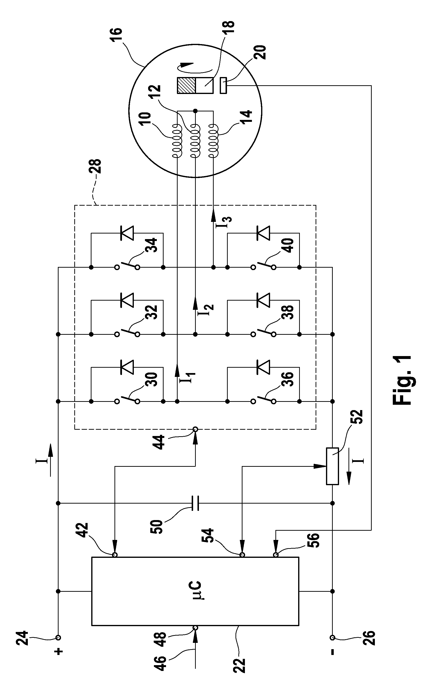
[0011]In FIG. 1 windings of a three-phase, electronically commutable DC motor 16 that are in a star connection are designated by 10, 12, and 14. Said DC motor cooperates with a permanent magnetic rotor 18. The respective position of the rotor is monitored by a sensor device 20, which supplies the signals concerning rotor position to a control unit 22 embodied as a microcontroller. The sensor device is embodied in a known manner with at least one Hall element per phase and supplies at least two rotor position signals per phase with each electrical revolution of the rotor. The Hall sensors evaluate either the field of the working magnet or a separate sensor magnet with the same number of poles and are arranged such that, in the case of a three-phase motor, six different rotor positions can be uniquely derived from the three signals (3 bits), offset expediently by 120° el.

[0012]The power supply for the motor 16 and the control unit 22 supply a DC voltage network with a positive pole 24...


PUM


Abstract

A method is proposed for supplying electrical power to a DC motor (16) which can be commutated electronically via a semiconductor power output stage (28), preferably a three-phase DC motor, through which a control unit (22) passes current in blocks, corresponding to the signals from a rotor position sensor (20). Current is passed through the motor (16) variably in steps, in such a manner that the magnitude and / or the duration and / or the trigger angle of the current blocks can be varied as a function of the rotation speed and / or of the load, with respect to the profile of the induced voltage (E).

Description

BACKGROUND OF THE INVENTION[0001]The invention relates to a method for supplying electrical power to a DC motor which can be commutated electronically via a semiconductor power output stage, preferably a three-phase DC motor, as described in DE 102 47 900 A1. This document discloses a method for supplying electrical power to a DC motor that can be commutated electronically having a control for the phase currents of the motor, which control receives as control signals, among other things, signals from a current sensor in a common lead of the semiconductor switch of the power output stage as well as signals from a sensor device for the rotor position. Power is supplied to the motor in this case either in the form of the block being energized with current blocks of 120° el respectively or alternatively in the form of a sinusoidal application of current having a half-wave duration of 180° el. In this case, even though using 120° block energizing permits the use of a simple and cost-effe...

Claims


Application Information

Patent Timeline
Patent Type & Authority Patents(United States)
IPC IPC(8): H02P7/06
CPCH02P6/10H02P6/142H02P6/15H02P7/28
Inventor WILHARM, TORSTEN
Owner ROBERT BOSCH GMBH
Learn More