Stator winding pattern for reduced magnetic noise

a winding pattern and stator technology, applied in the direction of windings, generator control by field variation, electric generator control, etc., can solve the problems of reducing the efficiency of stator windings, and exhibiting a significant level of magnetic noise, so as to reduce the noise level and mechanical vibration, reduce the noise level, and reduce the effect of torque rippl

Inactive Publication Date: 2005-03-08
BORGWARNER INC
View PDF18 Cites 28 Cited by
  • Summary
  • Abstract
  • Description
  • Claims
  • Application Information

AI Technical Summary

Benefits of technology

A generator with the proposed stator winding pattern generates electricity while creating less torque ripple than a machine with a conventionally wound stator. Since torque ripple (or variation in drive torque) is a major contributor to generator magnetic noise, a reduction in torque ripple produces low

Problems solved by technology

There are several disadvantages with conventional generators.
One disadvantage of generators of the type having a single, three-phase stator winding is that they exhibit a significant level of magnetic noise.
Another disadvantage pertains to generators of the type having multiple stator windings.
Stators with an increased number of teeth are more difficult and expensive to manufacture than a

Method used


Image

  • Stator winding pattern for reduced magnetic noise
  • Stator winding pattern for reduced magnetic noise
  • Stator winding pattern for reduced magnetic noise

Examples


Embodiment Construction

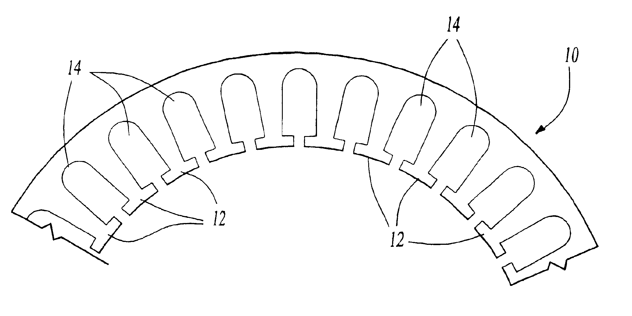
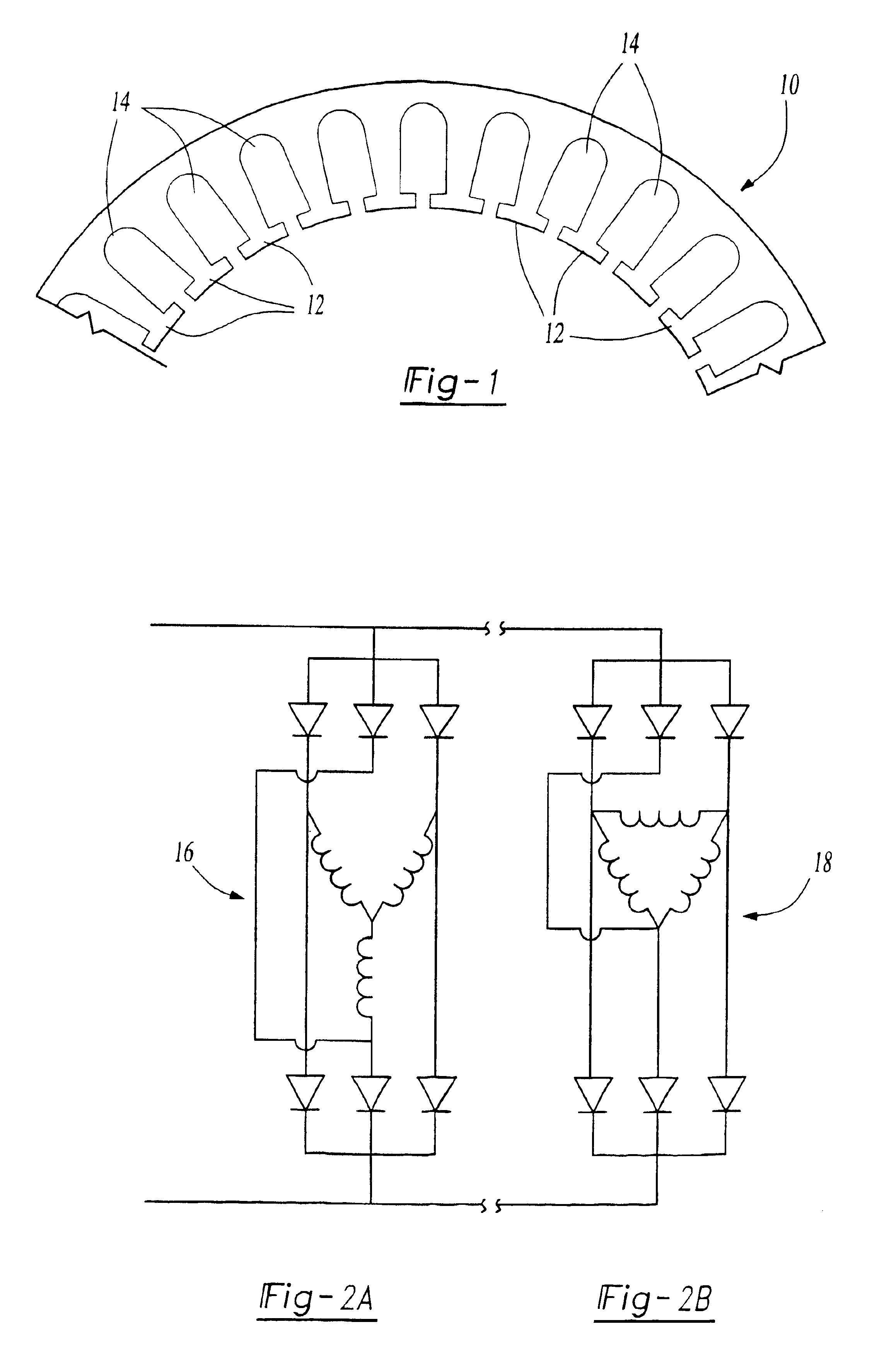
Referring now to the drawings, as is shown in FIG. 1, stator 10 has a generally annular shaped body portion with a plurality of radially, inwardly extending teeth 12 defining a plurality of slots 14. Each slot 14 has a radially outermost, closed end as well as a radially innermost, open end. The number of slots 14 in stator 10 is selected to be, and is dependent on, the number of rotor pole pairs n and the number of electrical phases p. In a preferred embodiment, the number of slots 14 in stator 10 is equal to 2×n×p, where n is the number of rotor pole pairs and p is the number of phases. In one embodiment, the number of rotor pole pairs is six yielding a total of 36 slots. This total number of teeth for a dual stator winding type generator is reduced relative to conventional generator configurations known in the art, which may have 72 slots for a three-phase, six pole, two stator winding generator. This reduced number of teeth reduces manufacturing cost / complexity, also resulting i...


PUM


Abstract

An electrical generator having a stator, a rotor, two windings, and a rectifying circuit. The stator has a first winding arranged in a wye configuration and a second winding arranged in a delta configuration. The wye winding is wound in a full pitch pattern around three stator teeth while the delta winding is wound in a short pitch pattern around two stator teeth, or vice versa. The wye and delta windings are connected to a single bridge rectifying circuit.

Description

TECHNICAL FIELDThe present invention relates generally to electric motors, alternators or generators, and, more particularly, to a winding pattern for use in the stator of an electric motor, alternator or generator.BACKGROUND OF THE INVENTIONGenerators are found in virtually every motor vehicle manufactured today. These generators, also referred to as alternators, produce the electricity necessary to power a vehicle's electrical accessories and charge a vehicle's battery. Generators must produce electricity in sufficient quantities to power a vehicle's electrical system. Furthermore, generators must produce electricity having the characteristics necessary to be compatible with a vehicle's electrical components.A generator includes a stator and a rotor, as seen by reference to U.S. Pat. No. 5,382,862 to Ward et al. In most generators, the stator consists of a metallic core and a current-carrying winding or windings in which electromotive force is induced by a changing magnetic flux. ...

Claims


Application Information

Patent Timeline
IPC IPC(8): H02K3/28H02P9/00H02P9/02
CPCH02P9/02H02K3/28
Inventor BUENING, DUANE JOSEPHKREFTA, RONALD JOHN
Owner BORGWARNER INC
Why Eureka
Try Eureka